Hello! I am trying to place two hexagonal elements within a hexagonal grid. I would like the two elements to alternate in this grid, to then create a kind of brise soleil on the facade. I tried various solutions, but he didn’t take one of the two elements or he overlapped them in various ways, I wanted to ask you if you knew a method to not make them overlap? Thanks in advance for your cooperation
prova griglia.3dm (3.7 MB) prova.gh (11.9 KB)
prova_2020Sep5a.gh (20.8 KB)
Using Flip Matrix (yellow group) gives a slightly different result:
1 Like
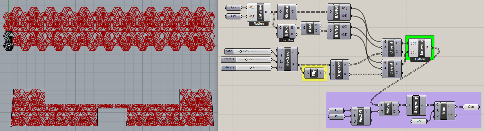
I think the full pattern looks better using only one of your Crv inputs?
prova_2020Sep5b.gh (15.3 KB)
Thanks this is amazing! I also thought it was more beautiful, but I’m afraid it will look like a lace doily, no?
I ask you one last tip, to make it a unique mesh, what do you recommend? I don’t want it to split into many elements and I don’t want to group it in Rhino.
Maybe a more complex Dispatch pattern? The second Crv is not a symmetrical pattern though.
Instead of grouping and trimming curves, you could use Boundary Surface and Brep Join to end up with a single “Open Brep” polysurface?
prova_2020Sep5c.gh (20.5 KB)
1 Like
Yes, I think I’ll do the second element again. I wanted something simple because the other element is more complex.
Oh yeah, I didn’t think about it. It seems that this works well. Thank you so much for your help, you are very kind 
Here’s one example of a more complex Dispatch pattern. It was done in haste so is highly specific to the data tree structure coming from Flip Matrix.
prova_2020Sep5d.gh (24.7 KB)
Unfortunately, the Boundary Surface “trick” doesn’t work with your second hex pattern and I didn’t take the time to figure out why.
2 Likes
Oh wow thanks! Don’t worry if the Boundary Surface trick doesn’t work, you’ve already given me several very good alternatives. Thank you very much! 
So, I tried to fix the problem. I have seen that as long as I do not connect the edge curve of the facade to the Extrude command, the Split Brep command seems to work correctly. As I connect the facade, it turns orange. In your opinion what could be the problem?
Without seeing your file, I would only be guessing, which is a waste of time.
Try repeating that ten times per day and see how it affects your attitude… 
Click on the little square at the top right corner of the orange component to read its error message.
Sorry i forgot to upload the file  prova_vari pannelli.gh (22.6 KB)
The component tells me “Split did not succeed”.
It looks like you changed the Rhino file because the second hex pattern is uninitialized?
The orange component circled in your image is Extrude, not Split Brep. There is no wire connected to its ‘B’ input. When I connect the perimeter curve to it, it’s not orange anymore, it works.
Why did you extrude the trimmed curves vertically??
Pottery Barn rule applies here: You broke it, you own it.
In the image I circled Extrude, because I wanted to show that Split Brep was no longer orange if Extrude was disconnected from the building boundary. When I plug it in, then Split Brep turns orange and Extrude gray. I was trying to fix Boundary Surface trick that was giving problems yesterday. Sorry.
I solved the problem!!! I break it, I remake it
And yet you didn’t share your solution by posting a file. Close but no cigar.
Here is the file
prova_vari pannelli 3.gh (23.5 KB)