Hi!
I’m working on a 3D model of a guitar bridge. It’s pretty simple and straight forward, but it’s taken me a lot of time to pull it, and I’m pretty sure there’s a simpler better way to do this.
What’s troubling me is the top bevel on the corners of the model. What would be the most efficient way to do this, since I have all the 2d lines. I thought of using Surface Network, but I have to add a lot of additional lines to make if work.
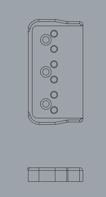
Hope I was clear enough. I added the Rhino file for clarity. sample file.3dm (250.1 KB)
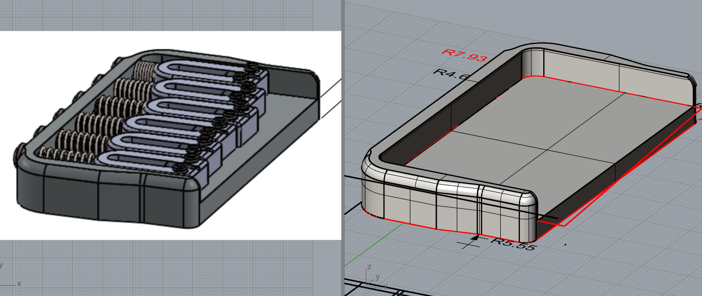
That “top bevel” appears from here, to be a fillet.
I would make this from 2 separate extrusions union’ed together: The base plate, and the side/back plate that supports the intonation adjusting screws. I would copy and keep a copy of the parts before union’ing. I even often add points to their height, so if I have to redo it for some reason, I know the heights.
A variable fillet can be added later. You can add a point where you want the filleting to go down to nothing, so later when you fillet it, it will start in a specific place. I would make another copy of the part, before filleting.
The the holes can be added by using the solid make hole tool using a profile curve. The countersinks can be made either from subtracting solids to make the screw countersink, or the revolved hole tool, which I neglect for some reason.
Also, the inside curved surface is a little tight, I hope you filleting operation goes well.
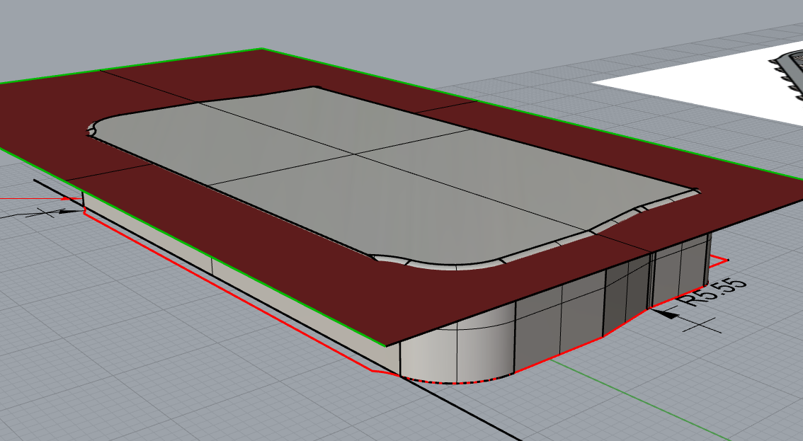
this looks like trimmed fillets, I mean like the original solid was bigger and then trimmed.
I would extend those arcs to get the original dimension like this:
Hello - one thing you will need to do if you have nothing better than this to go on, is make good guesses about the radii used on the actual part - what you have seems to be derived from a mesh - so in Rhino, using the Arc command > StartPoint is a good way (with End Osnap) to extract true arcs from polyline approximations. You’ll need to be careful to make sure things line up correctly, your polylines are a little messy - but it can certainly be done fairly easily - I did not frinish the job but you can get an idea how to proceed here-