Which components can model such a wavy texture on top of these Zaha Hadid vases?
Hi there.
Its a bit non-specific your question, don’t you think? I believe there is many ways to do this in Grasshopper. But my first guess would be to try something with the help of “panelling tools” plug-in to get those wavy lines distributed over a base surface. Later "weaver bird"plugin components to get a smooth mesh for your final geometry.
Thank you. Yeah, I know, it’s a very noob question ) But this way I have a direction for learning GH.
You’re welcome.
There is actually a lot of good tutorials out there for all levels of knowledge. Plus the community is very helpful and that includes the developers which still amazes me.
A quick way to understand how things work in grasshopper is to repeat a project of someone else in a larger video tutorial. I did one of lynda.com and one from digital tutors but there is a lot of profound free stuff too.
But for your project you could start with figuring out how to distribute things on a surface:
or
http://discourse.mcneel.com/uploads/default/19514/7692509422835f09.png
enjoy
I am a big fan of Zaha Hadid btw LOL, saw your post few days ago and I bookmarked it until I have free time to give it a try. so probably this is a little bit too late, but I will try to help anyway…
IMO there are several way you can model such texture.=
Option A = Using Materials u can unwrap ur UV Surface and paint Opacity Map in Photoshop. then put them back on and do a rendering. this is the fastest but it doesnt give you true geometry.
Option B = Using Grasshopper with Interpolate Curve and then Shift the Data to whatever point you need using Shift Tree Component. this can be a little bit hard especially for the part where the “Wave” starts to move randomly. this will give you the smoothest geometry result compared to the next option.
Option C = Convert NURBS to Mesh, since I assume the vase is a 5 sided cylinder mesh, just carefully model 1 side with grasshopper mesh component. download an add on for Grasshopper called MeshEdit and they have some useful Mesh component to help you with this. finish it up with Topologizer (also an add on) to make sure the mesh is clean.
once done, use rotation with copy enabled… at the end, use Weaverbird to smooth out your mesh.
I use Option C about halfway through (that zig zag wave) and got frustated after about 1.5 hour so I ended up cheating the process by sculpting the lower part (the part where the wave is slowly merged into solid). but if you are patient enough and spend more time carefully model the vase with good starting curves, you will have no trouble at the end.
I messed up the proportion and the curve at the very beginning so conversion to Mesh wasnt perfect, the point is to carefully plan your component before starting to fiddle with data tree in Grasshopper.
if you are talking about “material” for rendering, I would go for Option A. faster and the result is fine if it is not a close up shot.
I will try to redo it again if I have time and Ill let you know once I am finished
hope that helps
1 Like
Thank you for your help. I meant real geometry for later manufacturing.
And I’d prefer option B as the most elegant.
Do you know what component can project this wavy lines on a surface?
Btw, are these waves on your model holes? Because on real vase they are extruded.
from the picture on your original post, the Vase on the left is made of holes, while the one on the right is a combination of both holes and extrusion thickness with gentle tapers as extrusion profile.
yes, option B perhaps the most elegant way to go as it will give you the greatest control over the whole surface.
u can use surface closest point component =

any point will be projected to the surface in a straight line (closest point).
and u can get data from Surface Normal direction to drive points via Greyscale Map (abit like how displacement map works)
however, u cannot create “holes” with this method, u can just get a result like applying displacement on Rhino Native command
the reason why I recommended Mesh-component is because you can see a “slight” randomness on the wave profile. it is subtle but I think thats what make Hadid Vase looks artistic. it is easier I think to randomly “jiggle” data tree on a set of Mesh points. also, assigning holes is just as simple as culling out Mesh faces. with these 2 components =

also from what I see on Hadid image, she uses SubD (mesh-based) to model the Vase. u can see the pinching “Artifact” left over from deleting faces due to smoothing algoritm right at the merging point between Holes and Solid. where as if she uses “trimming” method, those pinching wouldnt be visible.
if all method seems to be a problem you can always go for a “manual” approach with native rhino command, projecting Curve and trim it one by one.
perhaps you can also get a python-script based-approach, some dudes on Grasshopper3D are very good at scripting and they can help you to write a useful script for this. ( there is a guy named “peter” he often post his own Script )
Thanx again.
Surely this textures on vases are not holes, it’s just a polished silver reflections.
(Btw it’s photos of real vases, not models, but I’m sure they used GH ) )
Here’s the making video.
my mistake then, if that is not a hole then it is much easier  , I will try to recreate that then with displacement method, give me time and Ill post it here once I am done
Hi there, here you go,it is midnight in my hometown, I tried to model it as fast as I could and give it a little render otherwise it doesnt look good with just viewport printcreen… since it has no holes, GH definition is not very complex but most work is actually doing manual tweaking at the very beginning.
so if you are okay with the look then tomorrow I will break down the process one by one for you to get a better understanding about the process.
hope that helps
2 Likes
Extruded waves look great!
It would be perfect if you explain how you achieved that. And if it’s possible please share the definition.
Ah, good then. Sure. I am still at the office right now, i will compile and explain the process one by one later at night after work (at my local time  )
)
Hi there!
If you don’t have time to compile an explanation, please upload the definition file, I will try to dig it myself.
Hi, sorry for the late reply, I was busy with deadline and had to work overnight.
here is the break down process of what I did from the beginning until final model.my office strickly forbid to give away any model or GH def done in this office. however I can show you printscreen of how its done, you can just find the component on GH canvas and just follow the image which component attached to which parameter and so on.
so here we go =
first, you can start to build a rough approximation of the base geometry, this is a crucial step and make sure everything is made of Quads (4 sided)
otherwise the definition will not work later…
you can create the base geometry via “meshfrompolyline” or you can start with NURBS Srf later on convert it to mesh its the same anyway.
and you will need Weaverbird Plug in to subdivide your mesh. since this is actually a 6 sided cylinder, you can isolate 1 side out of the entire mesh to keep thing simple.=

second step, you will need kangaroo add-on for grasshopper, assign your mesh to mesh component, and then create 2 control curves as guides. (see picture and you can experiment with control curves to give you and kind of pattern you like.)
assign 2 control curves to [curve right] and [curve left]. once your are done, extract all points on your mesh and assign half the points to [point right] and the other half to [point left].
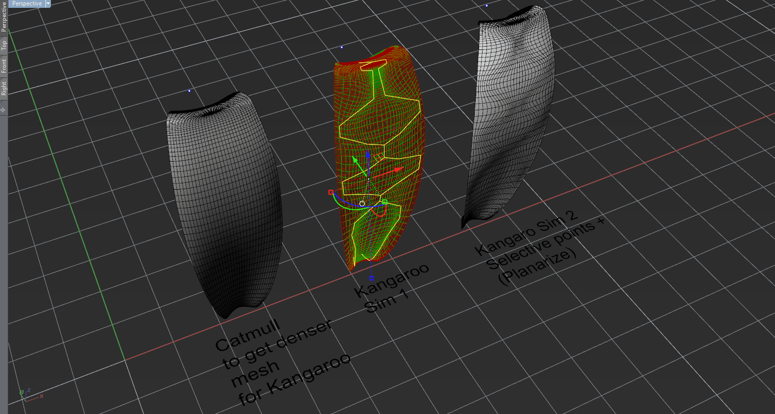
put those Kangaroo component on the canvas and arrange them to look like image below =

double click [boolean toogle] to start the simulation,
while sim is running scrubs slider [variable Y] to control how “stiff” your spring is. (all those number depends on the size of your model)
to be honest I never get a good result in 1 try, so normally I run the simulation couple of times and select the points that I think needs to be modified further and plug it back to [point right] and [point left] component.
adjust your guide curves on Rhino viewport and see changes on the fly. once you are satisfied, bake the result and close GH (Kangaroo will make your compute runs slower)
perhaps you would need to refine the result because normally it will not be smooth ( abit jagged ) this can be done manually in rhino.
third step, Offset Mesh face (Solid) you can do it via Grasshopper by carefully selecting mesh faces on data tree or just do it manually in rhino, in this case I did it manually in rhino as I dont want to waste too much time fiddling with definition, once done rotate your mesh 6 times around its center point (copy enabled) you will get this result =

Final step, subdivide your final geometry one more time to give it a smooth curvature all the way around. now your model is ready for rendering. since I dont have any rendering engine installed in rhino, I export my model to other software = (you can search other post to find good renderer engine in RHino, to be honest I am lacking of experience rendering inside rhino)

did a little bit of scultping to give it a little bit of randomness. (you wont need this actually).
add environtment IBL, apply metal shader, set to low setting and hit render

I hope I explain it clear enough, I am sorry if I reply a little bit too late,
and hope you can understand my english too, I am pretty sure I make tons of grammar error
cheers.
the reason why I dont use Option B or C as I mentioned on the previous post is because I realized there would be too much work to do and I wanted to finish it in less than 4 hours, so I pick kangaroo as I think that is the fastest to set up and the result is pretty much okay.
but of course the even faster one is by using image displacement =P in which then we will not have this discussion.
2 Likes
Wow! Thank you very much!
Will try to deal with your definition )
Btw, what is the program on the 5th screen? Maya?
sure no prob :), yes, it’s Maya.
@Runnie , would you be willing to go into a little more detail (more screenshots) showing how you created the base mesh from surfaces or polyline? Thanks.
