Hello,
I’ve been creating clay vessels with Rhino and Grasshopper and a clay 3D printer. I saw this new slicer that helps with the instability of the material. Looks to me like it just changes the path to squiggly lines that make a thick wall. It’s not available to the public. Is there a grasshopper plug in that will do this?
I don’t think there’s a “ready made” equivalent plugin to do that in GH, but for sure you can manipulate the planar path-curves in GH to do something similar
here I clearly see the seam, so their algorithm works both for planar layers like in this example, but also in “spiral one-curve toolpaths” vase-mode-like, as shown in the initial frames of the video:
about vase-mode, for sure it works pretty well for geometries with axial simmetry like shown here
I doubt it would work that nicely also for vase-mode on geometries with non-axial simmetry… it’s a pretty complicated topic
this slides from the video state things that -to my eyes- are in contrast with each other (and with the slide graphic itself):
wall thickness does not look at all constant throughout the section, it’s thicker on top and bottom, and much thinner the closer to the belly… maybe they missed the word “minimum”, like “Stability is preserved by maintaining a constant minimum wall thickness throughout a 3D printed form” ?
also, “Traditional Path: constant layer thickness” and “WeaveSlicer: constant wall thickness” (as if layer thickness wa not constant in their slicing, but it is in their graphic…)
there’s a little bit of confusion here, but also maybe they don’t want to just give away all the details and results of their research in a presentation video
@inno Thanks for your reply. I’m still new to this. I thought there might be an easy way to write an algorithm that could make the tool path similar to what they are doing or better yet a plug in! I guess I could just create geometries on the surface that might generate those paths…
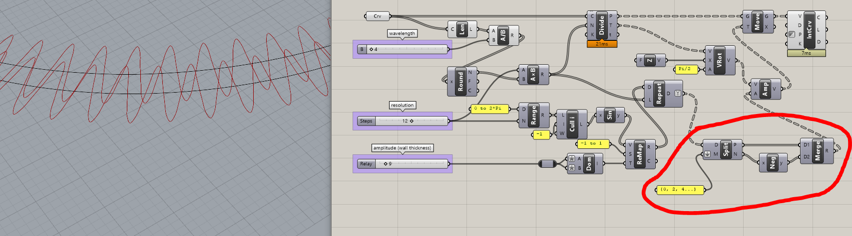
I think the easiest solution would be to divide the toolpath curve into subcurves of lengths equal to the desired wavelength, then define a certain “resolution”, then push/pull points in/out by vectors of amplitude equal to a sine wave of same resolution and desired amplitude
for instance, this might be a very basic approach that works fine for circles:
when you are dealing with multiple curves like an array of different layers for a 3D print you might want the sine pattern to be reversed for odd layers, like whatever was pushed inside in the previous layer should be pushed outside
this method doesn’t work well for sharp corners, as @inno noticed
to fix that, you have two options. either fillet the corners with a radius large enough, or manage them somehow → an easy method would be to split the curve at kinks. then join the resulting sine/cosine curves and fillet them.
For the sake of conversation I thought I would share my version of this type of slicer I made beginning of this year. It uses a loop and a hash that is customizable for width and depth. It’s still got some funkiness to it as I had trouble continuously orienting the hash towards the center in a cohesive way but it was really just a day or so of messing with it then on to other projects. I also made it with the intention of throwing lots of geometries at it but it’s totally untested. Like I mentioned just food for convo… Fatty Hash Loop Share.gh (1.1 MB)
I’ve been doing 3D printing with a regular FDM printer for quite a while. For now I’ve settled on PrusaSlicer as my slicer of choice. Prusa has this web page that describes all the things it’s slicer does: https://help.prusa3d.com/category/print-settings_212
Since they make their source code available for free I thought maybe it would be easier to adjust their code to accommodate the unique requirements of clay printing.