Verifying developable surfaces

Some observations on developable surfaces in Rhino

  1. Given two curves in space, for example a sheer line and a chine line on a boat that is to be plated with steel or aluminum:
    We want developable surfaces, as that is necessary if a flat plate is to be rolled into place during construction. In Rhino we have DevLoft, which normally gives a good result, or the plug-in, D.Loft, from Evolute, which I have found to give better results, and is easy to use.

I have seen in many forums and other places on Google that the use of a 2 rail sweep has often been recommended.
A 2 rail sweep will, in many cases, NOT produce a developable surface, and it is easy to be fooled. It will produce, possibly, a “nice” looking surface. But if you use that surface to cut transverse frames, you can run into serious problems. If you were just building a stitch & glue dinghy you might never know the difference. But if it is a larger boat, and it is expected that the plate will lay nicely onto the transverse framing, then you can run into serious problems.

  1. Ways to verify the developability of a surface:

There are several analysis tools that can be used: Curvature analysis, draft angle analysis, the environment map, and Zebra. They all seem to be reasonable tools for evaluating the developability and fairness of a surface, and are tools that should be used.
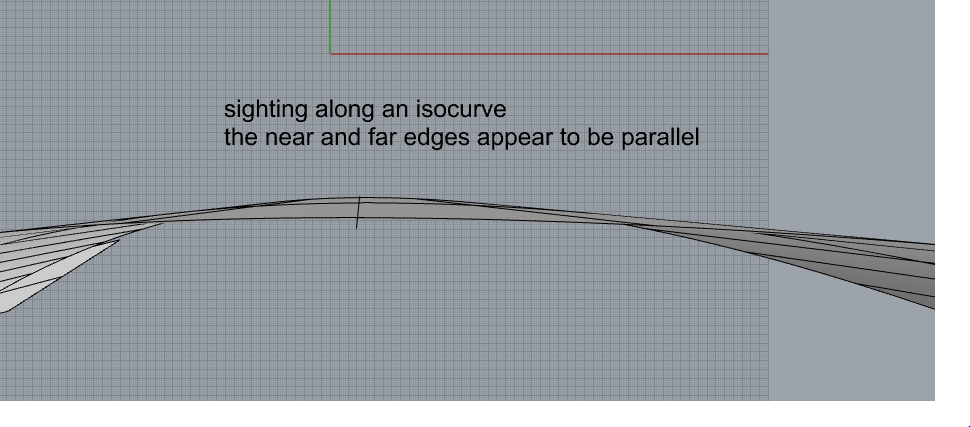
Another, more intuitive and visual method, is to actually sight along an isocurve. This is easy to do, in particular if you use a 3D mouse. Just orient the surface in space until you get a clear view straight down one isocurve. The surface edges at both ends of an isocurve on a developable surface will appear to be parallel, at that location, which means that they lie in the same plane. This check can easily be done at a number of isocurves, and can verify that the surface is truly developable. It is also easy to see when the surface is NOT developable, as it will be very obvious that the two edges are not parallel.

In other words, if you have a truly developable surface in 3 dimensional space, then you should be able to lay a flat bar (surface) along any of its isocurves, without it cutting the surface. That is basically the definition of what it means when a surface is developable.

Using the same set of curves, you can build a truly developable surface, or a surface using a 2 rail sweep. They may both look nice, but they are NOT the same surfaces. I have found that Rhino very often will unroll a surface that is NOT truly developable. And it is strange that unrolling a surface from a 2 rail sweep, and a developable surface from the same two curves, can result in two flat surfaces that are nearly identical. Normally, the developable surface will unroll with no change in its area, while the non developable surface will have some change in surface area. Despite that, the edge lengths may be nearly identical between the unrolled surfaces, and often the surfaces can be oriented to lie upon each other, and seem to be nearly identical. That can, unfortunately, lead one to believe that it doesn’t matter. But it does.

If the surfaces in the model are being used to cut transverse framing, and you use a surface that is not developable, the builder will probably realize that for some reason, as he tries to install the plating, that it does NOT lay onto the framing. In a small boat of 16’ to 24’, this can be a disaster. In a larger vessel, for example a large steel fishing boat, it can be a very expensive disaster.

I have developed a method to use basic commands in Rhino, besides the standard surface analysis tools, to verify the developability of a surface. I realize that sending out a cutting file for a large vessel- plating and framing- is a very serious undertaking, and making a mistake can be an expensive disaster. So any additional means to verify that the plating, which will be used in the 3D model to cut transverse framing, are worth using.

As a refinement on the method of sighting along isocurves, mentioned above, I have been using basic commands to actually generate a flat surface running along an isocurve.

I start by extracting an isocurve, and normally just leave it in place, on the surface, at the position of the visible isocurve.

    1. I draw a line normal to the surface at some point on the extracted isocurve.
    1. Then I rotate the isocurve about the line formed by the normal line, 90 degrees, making a copy so that the isocurve is still there.
    1. Normally I then extend the extracted isocurve at both ends to be sure it runs well away from the surface edges.
    1. Then I move the rotated isocurve to the end of the extended isocurve, and use it to draw a short line at the end of the extended isocurve.
    1. Then I use a 1 rail sweep to generate a flat surface that extends beyond the surface at both ends.
    1. (there are various ways of doing this, using a combination of commands)

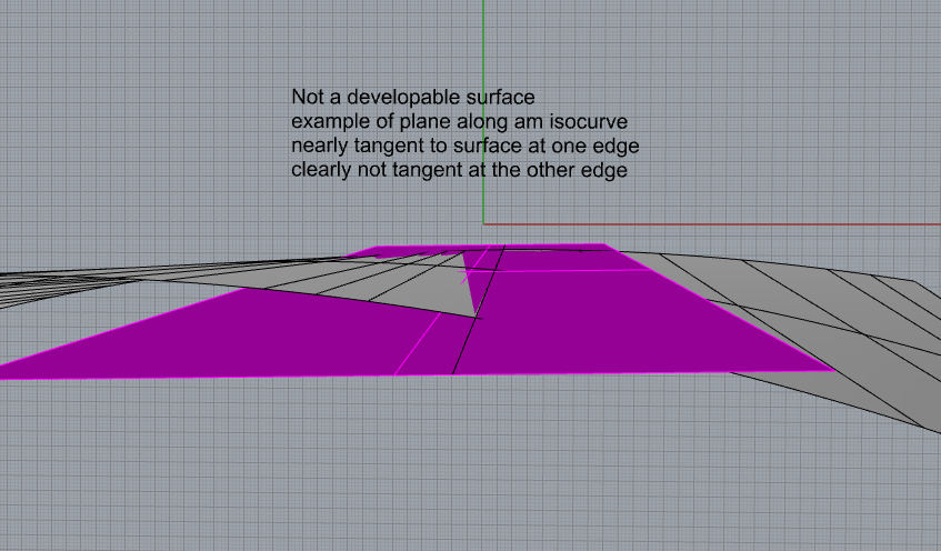
If the surface is developable, then that plane, which only needs to be several inches wide, will be obviously tangent to the surface everywhere.

If you try that routine on a surface that is NOT developable, like one made by a 2 rail sweep, then it will be at once obvious that the flat plane that you generated cuts into the surface somewhere.

This might sound like a lot of work, but it can be done at several places on a developable surface in just a few minutes, and gives visual proof that the surface is developable, and that it can then be safely used to cut transverse frames, as well as longitudinal framing if they are to part of the cut file.

I would only use this method at those parts of a surface that have a lot of obvious curvature, like plating wrapping a bow, or lower bottom plating forming the forefoot of a vessel. In areas that are essentially flat it is not necessary.


2 Likes

A quick way to assess if a surface is developable is to use the Curvature command. Pick a point, use Curvature, and look at the principle curvature circles. If one circle appears as a line, ie a circle with zero curvature and infinite radius then the surface is developable at that point. Also the zero curvature circle/line will be aligned with an isocurve if the surface is degree 1 in one direction.

Another way to check if a surface is developable (assuming the surface is degree 1 with two control points in one direction).

  1. Create a ruling line:
    ExtractIsocurve command in the degree 1 direction at the desired location.

  2. Create lines normal to the surface at either end of the isoline, or two other locations along the isoline:.
    Line command with Normal option. End OSnap makes it easy to select the ends of the isoline.

  3. Check for twist along the isoline:
    Angle command with the two normal lines created in the previous step.
    If the angle between the two lines is 0 then there is no twist along the isoline, and the surface is developable along the isoline.

2 Likes

I know about using the curvature circle, and forgot to mention that. I always use that as well. And I like the suggestion in your second response. A good way to do it. But I also like the more visual method, especially if there is a lot of money on the line. It just gives me some reassurance. I knew that there would be other ways to do this, so I appreciate that.
Thanks!

When a surface has a constant zero Gaussian curvature, then it is a developable surface and the geometry of the surface is Euclidean geometry.
Taken out of here

Use Surface Analysis (tab) - > curvature analysis (command)
image
click Auto Range. If the range is around 0 (zero) +/- some value and if it is within the required accuracy. Then it is developable.

Visually…Make sure it is green.

1 Like

Thanks for making the effort to write that down. It’s a very useful way to test a surface.

It’s essentially the way DevLoft works to find where to put rulings.

There are functions used in that process to evaluate a ruling between curves and return the amount of twist across the surface. That is very scale dependent - It measures the rotation required to make the tangent at one edge match the tangent at the other edge without considering how far apart the ends of the ruling are.

I mention that because it would be easy to expose that functionality so that you wouldn’t have to do the line manipulation.
It would also be pretty easy to script something that would do the same thing.
If that would help and if we can find a definition of how it should work, I’d be happy to help with that.

Lowell

Guassian curvature is a very common metric suggested for assessing if a surface is developable, but it has a significant drawbacks for assessing if a surface is close enough to exactly developable.

An exactly developable surface has exactly zero Guassian curvature. But what is the surface is not “exactly developable” as sometimes happens in design.

How small is small enough for Guassian curvature? That is a non-trivial question, and one that I have rarely seen an answer to.

Is 0.1 small enough? How about 0.001 - that seems like a small number? Or should it be even smaller, perhaps 0.000001?

Gaussain curvature has units of 1/length^2. If millimeters are the length unit then Gaussian curvature has units of 1/mm^2. If meters are used then Gaussian curvature has units of 1/m^2. So the numeric value for the Gaussian curvature of a surface will be 1,000,000 larger if meters are used rather than millimeters. A Guassian curvature of 0.1 if meters are the length units use is the same as 0.009 if feet are used, the same as 0.00065 if inches are used, and the same as and 0.000001 if millimeters are used.

A second drawback to using Guassian curvature to assess if surface is close enough to exactly developable is it is difficult to relate Guassian curvature to other measures such as the amount of twist.

Which method of the three in this thread are you referencing?

Does DevLoft use something other than minimizing directly measured twist when deciding where to place rulings? If so why?

Are those functions simpler than the method I outlined above for measuring twist across a ruling line?

DevLoft samples ruling lines and at the ends of each one, finds normals to the surface and does a dot product which yields the cosine of the twist angle.

If there is an advantage to doing anything more, it would be that the interface would be quicker - Pick a point on a surface and see the iso line through the point and the twist angle across the ruling as a number without moving any lines around or making more geometry. No new technology, just easier to use.

Sounds good.

That would be very useful.

Lowell

I made my post because I, like apparently like a lot of other people, wanted to find a way to visualize and verify the developability of a surface. I wanted something intuitive, something that anyone could see and grasp. This is something that any modeler could show to a builder, and they would get it.

I know from boatyard experience that you can take a flat bar and slide it along the surface of an unrolled plate. I had actually thought that it would be interesting to extract a series of isocurves, and include them when unrolling the plate, and then having the cutter mark them as etch lines, on the convex side of the plate, just to make it easier to slide a flat bar along. Of course, that would be a waste of time, if the plate had already been unrolled, and it was no more than a thought experiment. But that is what led me to the procedure that I posted and illustrated.

It did occur to me that there would be some smart way to do this. The suggestion by David is a step in that direction, but I am sure a script could be written that would automate the whole thing.

Of course, if we can be assured that the surface is developable, then one might say it is not necessary. But then there are all the other tools we use, so why not something that can be visual and intuitive.

When it comes to the real world, it can be very intimidating to send out a cut file, and initiate a build, which can represent a lot of money.

I would not know how to write a script for something like this, but if you could do that, I think a lot of people would find it reassuring.

Brian

Some nice comments about this topic here.

We used to mark segments of the ruling lines on curved steel plates to guide the brake operator, it worked well, when combined with templates to get the correct curvature in the part.

A real challenge with the developable tools is that success is so material dependent. It’s easy to make lovely developable surfaces for plywood boats that can’t be built because the plywood won’t bend the short way across the panel.

Eric

Yes, plywood can be a challenge. And it is helpful to have the tangents to a curve etched on a metal plate, and maybe some rulling lines as you suggest, on metal plates. Some shops are really good when it comes to bending up curves if they know the radius and the total degree of bend. Templates can be helpful. The real challenge is large bow and forefoot plates in steel or aluminum. It helps to have targets marked on the plates as well as the supporting structure, like etch lines where the plate should lay against the frames.
Brian

Judiciary marks?

@Lowell Instead of using the dot product of the normal vectors consider using the magnitude (or magnitude squared) of the cross product of the unit normal vectors. The advantage of using the magnitude of the dot product (sine of the twist angle) is it goes to zero as the normal vectors become parallel, and the rate of change of the cross product is proportional to the twist angle. In contrast the rate of change of the dot product approaches zero as the twist angle approaches zero.

Brian - That is kind of what caught my attention in your first post - the idea that there is a geometry of what happens when you bend a rigid plate that’s sometimes not clear. Probably packaging that all up into a quick command could detract from the understanding of that geometry, or at least not help make it clearer.
It could still be useful for evaluating the surface.

Lowell
I think you are right, that it is worth doing the simple procedure that I outlined, or something similar, so that you have a visual check on the surface. I very often just do as I first suggested: sighting along an isocurve and looking at the near and far edges. But in the case of very curved surfaces, such as bow plates or the forefoot of a boat, then it is worth doing some kind of check, and it only takes a few minutes.
I have found that DevLoft is a big improvement over the earlier tools in Rhino 5, and I very often use several of the tools available, including the plug-ins from Evolute. I like to make several versions of developable surfaces, leaving them in place, and then project a line through them, and pull the projections off to one side for inspection.
They should be very close to each other, i.e. nearly the same line. That is just one more visual inspection that can be done.
Running a curvature circle along the surface, and seeing how well it aligns with the isocurves is a an easy method, but I sometimes find it gives some strange results. I have found that it is, as usual, very important that the curves used to generate the surface be as simple as possible, so I usually try to refine and rebuild the curves, as long as they remain where they have to be.
Brian