I work for a welded aluminum boat manufacturer in which we use Rhino to create our 3D models. We then unroll our parts to be cut on a plasma CNC machine.
For the most part creating patterns has not been an issue but we seem to end up with some inconsistencies between what we model and what can be created in reality.
We currently draw our hull and chine curves as fair as possible and run a 2 rail sweep down the length to produce our hull surface.
I have briefly looked at the DevSrf command with the hopes of being able to produce a more realistic and developable surface but I not really sure how the command works or how to adjust the rail curves to create the surface.
If someone has had success using this command or understands its capabilities and would be willing to give me some advice on the topic I would be very greatful.
Attached is a quick example of boat hull surfaces using DevSrf. Boat01S.3dm (146.1 KB)
The bottom is relatively simple to do. The side requires a “trick” because of the characteristics of true developable surfaces.
What I don’t understand with DevSrf is what kind of adjustments you need to make to the rail curves or the settings once you activate the commands. This is an example hull rails.3dm (184.4 KB)
the hull rails I am trying to create a surface between using DevSrf.
I’m not sure what adjustments I need to make it work.
i adapted your Curves by simple setting the controlpoints of the curve in the straight part:
set x and y to the same value
_setPt
I build the surface with _loft using the developable Option
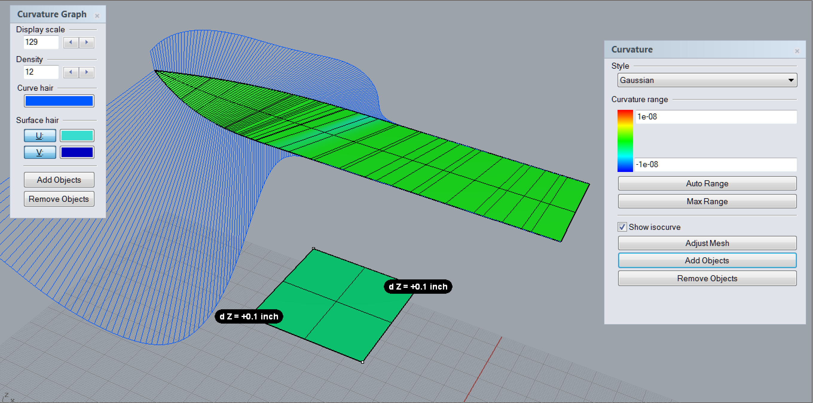
afterwards you should check the Gaussian Curvature of the surface.
Use
_curvatureAnalysis
Make sure to adapt the Analysing-Mesh (the Mesh-Option of this command)
@davidcockey@seanprokopec
Edit: new screenshot with adapted Curvature range
If you need a reference for Curvature-deviation to non-zero gausian curvature
digital: draw a planar square and lift two corners / CVs
Workshop, physical world: lay a peace of sheet metal on the floor and lift two corners…
somehow those two values should not be to much apart … as a starting point
not sure. the approach also works with _devSrf and the parallel Planes option.
check the deviation of the initial crvs with the resulting surface Edges:
_crvDeviation
the _loft command is maybe a bit older then _devSrf, while _devSrf is more experimental
_loft is closer to the initial crvs
_devSrf result is simpler / less control points.
At least there will be a plugin equivalent to DevSrf available for v6. I’d like to do some more work in that area, and its just dependent on workload at this point. Lowell
I generally have not seen fewer control points with DevSrf than with the Developable option in Loft.
Edit: Previous comment removed because I don’t know how much Tom changed the shape of the curves in his example.
Guassian curvature is tricky to use to check how close a surface is to developable. The scale in Tom’s screen capture will have almost any surface between the points as green. A better check is to use Curvature and check that one of the principle curvatures is zero (straight line rather than circle) or “close enough” to zero (large enough radius circle) everywhere.
I suppose the main reason I’m asking these questions is to try to figure out what people would consider the most accurate representation of the hull surface.
I understand the Gaussian Curvature scale has a big factor in how much a surface strays from developability but not at what point it begins to become a noticeable effect.
Does it require much adjustment of the rails to produce a fair surface as well as much fairing to the rail curves?
If I was using the previously uploaded curves as a starting point is the much you think I could do to create a surface using DevSrf that would actually have some reproducibility to it?
Other than following our previous methods of using a 2 rail sweep, I haven’t yet been able to see what can really be done using DevSrf that will produce something more accurately.
We produce almost solely warped aluminum hulls and I can see where some of the error can arise when trying to determine the twist difference between the keel and chine, but I was hoping I would be able to figure out a method of trial and error adjustment of the rail curves using DevSrf as a check for developability.
I just don’t fully understand the options or capability of the command and haven’t been able to find much info on it.
A warped surface with straight edges and straight section curves will not be exactly developable. That’s fundamental geometry.
@seanprokopec The keel curve you posted has some reverse curvature. That can cause problems with DevSrf. Is it intentional? Is there a reason for 21 control points when the curve has a simple shape?
The reverse curvature is definitely not intentional, it was the result of using Rebuild. I had quickly pulled those curves off an old model that we are looking at trying to remodel due to build problems.
With curves such as these would you recommend trying to reduce the number of control points as much as possible, then using DevSrf?
Also, it’s the stations where I think most of our build errors have been occurring. When we are using the 2 rail sweep, we are estimating the curvature in the stations. Sometimes it will create a surface that will unroll, other times it won’t.
Here is an example of a recent hull that took shape fairly well. hull curve.3dm (187.7 KB)
Yes, reduce the number of control points to the minimum needed for the desired shape. [quote=“seanprokopec, post:14, topic:44505”]
Also, it’s the stations where I think most of our build errors have been occurring. When we are using the 2 rail sweep, we are estimating the curvature in the stations. Sometimes it will create a surface that will unroll, other times it won’t.
[/quote]
The curvature needed at each station can be found using DevSrf, but it requires extending one of the curves with the needed shape. When I have a bit more time I’ll post an example.
I have found an article describing the process for developing and I have been trying to apply it my keel and chine curves to develop ruling lines.
Does this seem like a reasonable alternative to DevSrf ? https://www.boatdesign.net/articles/developable-surfaces/
You might like to check out Dloft. I use it to get accurate panels formation for making sails and I am extremely happy with it. http://www.evolute.at/software-en/evolutetools-d-loft
I’m not associated with evolute tools in any way, I just like the software
How special are your curves relative to your final product? It seems to me that you could use a conic surface generated by using rail revolve that would be 100% developable and, at least for the curves you’ve submitted in this thread, it would probably be close enough to your intent to be an acceptable solution. I think using this method would go a long way to solving your build problems.
The trick with devsrf (and it is tricky to get the hang of) is to think of it as a parametric plugin. It will respond to you changing the input curves, showing you the basic ruling lines between your curves. You can use any normal rhino commands to change and analyse the curves while devsrf is running. Green lines are perfect dev rulings, red are within tolerance, no ruling lines in a particular area mean there is no developable solution.