I am dealing with a big uncertainity when generating fabrication data. I have a ruled surface that I need to unroll. There are many openings (letters) in that surface that have to be unrolled together with the surface to be laser cutted.
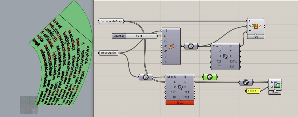
I’ve noticed that when I unroll curves together with the original surface, I get a different result than when I map curves to previously unrolled surface (which is a waaaay faster approach). First, I assumed that UV space is the same for both approaches, but it is not (verified by measuring edge lengths of source and unrolled srf).
The problem is that the fabricator already got data generated using “Map Curve” approach and they prepared the piece for rolling and it will possibly cost me a lot of $$$ because of this issue.
I’ve read this thread but overall I am not sure what exactly causes this issue. I expected that the UV space stays consistent. Does anyone know why this is happening, please?
Thanks for this suggestion. But I use iso trimmed surface so shrinking doesn’t make a sense. @dale Do you have an idea what’s going on here or what did I do wrong?
Hi Petr - Is the underlying problem you are trying to solve the slow speed of the process?
UnrollSrf does not try to maintain the UV distribution as far as I know; UnrolSrfUV does, but at the possible expense of accuracy - in this case a discrepancy of ~30 sq. mm.
Hello Pascal. I was assuming that the UnrollSrf is not UV destructive. Didn’t know about UnrollSrfUV as I was using Grasshopper. I tried to verify that UV is matching by mapping edge curves (FlowAlongSrf) and it was just fine. There was no reason not to trust the component, as majority of components keep UV space as is down the stream.
Now all unrolled parts are already laser cutted and I am facing a terrible and expensive issues thanks to that distortion. I wish I knew this before. There should be some sort of warning message… What do you think?
Hi Petr - yeah, I can see there is a nasty problem for you, and perhaps there is some way to warn users. That said, flowing edge curves back from UnrollSrf output does not look so good to me -
Yes. This one edge is already distorted and it’s the trimming curve. But in grasshopper, I was working with the original Untrimmed surface (I was even thinking that the trimming might cause some issues so I tried to avoid it as much as possible.
Don’t you know why V direction stays undistorted?
Possible warning should be an amount of distortion? This could possibly be done by unrolling the surface together with some points and comparing them with the same points just by evaluateSrf - and measuring the distance of the result. The value informs the user about possible distortion (and also where that happens). Knowing that issue before, I’d do this and avoid the problem completely.