Hi! I’m a begginer with grasshopper and would like to recreate this project from Uni and dont know how to begin (tried creating random points within a similar shape then triangulatinf them but didnt work) Any suggestions on how to begin? It doesnt need to be exactly as the fotos but a similar thing


Your choice (with regard aesthetics) is excellent: bravo. But there’s bad news around as well.
Anyway … after doing the rnd Pts … use Proximity and then continue using VV Connectivity (*) for the envelope pieces (random? prox to something? you tell me). Notify if you want a C# that does similar things.
(*) I assume that the T is about that - but why paths have 2 dims? (since that thing can’t detect Islands in Graphs).


BTW: In fact this is way more complex because we must check the Graph/Truss for rigidity (not to mention Islands and members clash issues [cones/sleeves/tubes/etc]) . Rigidity means tetrahedra … thus that’s just a matter of dealing with VV Connectivity AND using ways to interact - on a per Node basis - with any candidate solution on the fly (GH is NOT interactive by any means). Since this type of thing is 10000% about aesthetics (for instance: I can barely imagine shading/cleaning constrains etc etc) … we need a robust solution/cost History management approach as well.
BTW: Real-life (or even “real-life like”) random trusses are the most challenging Parametric task known to man for various reasons - rather hard to explain in brief. I would strongly advise to postpone that kind of stuff … untill you’ll become some sort of expert (hope dies last).

I work with R5 : for the very limited usage (if any at all) that R/GH have in practice that’s all what I need, Other than that SubD has nothing to do with your goal: the triangles (that could be “inner” or “outer” in the Graph) are a classic task solely based on VV Connectivity handling - elementary stuff via code (C#).
But … do you know what Connectivity (*) is, what it serves and how to deal with such Trees? (assuming that you know what a DataTree is in the first place [the vast majority of beginners have no idea about these - custom to GH - collections] ).
Anyway - as I said - notify if you think that a C# that does that could mean anything to you (unless you have plans to walk that walk - HIGHLY recommended since you are in the broad AEC market sector)).
(*) given one or two Lists (of any Type) a Conn Tree (let’s talk one dim paths for simplicity) is the classic way to co-relate things: the path indices (per Branch) are the indices of the items in the first List (say the Master) and the items are the indices of the items in the very same (case one List) List or the other (case two Lists) , say the Slave List. That said in AEC Geometry is nothing without Connectvity.
BTW: If we forget closet Graph primary cirquits (a task NOT for you by any means) you can have tri/quad or tri+quad panels:


Not really familiarized with C# script. Kinda looking into it atm to see if I can use it on the Short notice
any tutorials to recommend?
That’s obvious: otherwise you would’t bother asking for any kind of help: you can do anything imaginable (and very very very fast) the code way .
Tutorials? well … I’m the wrong person to ask since I never use components. Meaning: cross fingers for a good Samaritan who likes them. If nobody appears … I could post a deresrticted entry level C# (kinda a black box for you) that would do what you want : Is very simple in fact : given the Connectivity is less than 5 minutes job (it checks min Angle [per triangle] and max Ratio [ditto] as well):

In the mean time see the Sandbox add-on: has a thing (forgot the name) that can extract VV, VE, EV Connectivity given a Line Graph (but can’t detect Islands and/or Bridges … meaning that his usage in real-life is highly questionable)
wow looks very interesting. I’m gonna look into it definitely (still have a looot of stuff to learn). For the time being, I managed to do it the hard way (and most likely inneficient). But guess its gonna be good enough for making some images. Thanks a lot for the help. This is how it looked in the end :

Very good aesthetics … pitty that you can’t code (but never is too late - or is it?).
Have in mind that this type of design needs a robust interactive policy: i.e. let the idiot (the computer) do some preparation/things … and then modify nodes on the fly - on a per node basis using various proper Clip Planes (Impossible to do it without code … while the idiot does a myriad solution validation checks required for some real-life/rational result - even on Academic level).
Some checks: Islands/Bridges in the Graph, Truss Rigidity, Clash in members, Filters (angle/ratio/edge lengths etc) for the “Panels” , “Panel” subsystems, FEA, maybe some Shading efficiency of the whole envelope … etc etc.
For instance see what structural week connections mean in some prox Truss (as the idiot does it … without any post action: i.e. a useless result). Weak dedection … well … you guess it: it’s just a few lines of code based on VV Connectivity (that is useless without Island dedection … that is useless without Bridge dedection).


All that prior Panel to Panel collision detection (in yellow):

As I said: for a real-life result (most notably: a large scale one) that’s rather the most challenging Parametric task known to man.
Tip: involving a computer for that type of design is the art of pointless (with regard the creative part of the story). Computers are just for adding 1’s to 0’s - until AI hits the masses [Armageddon].
Whoo, this brings back memories. I did a similar project back in 2007 using Maya for all the modelling. Peak Mental Ray physical sky look too, what a time to be alive ![]()
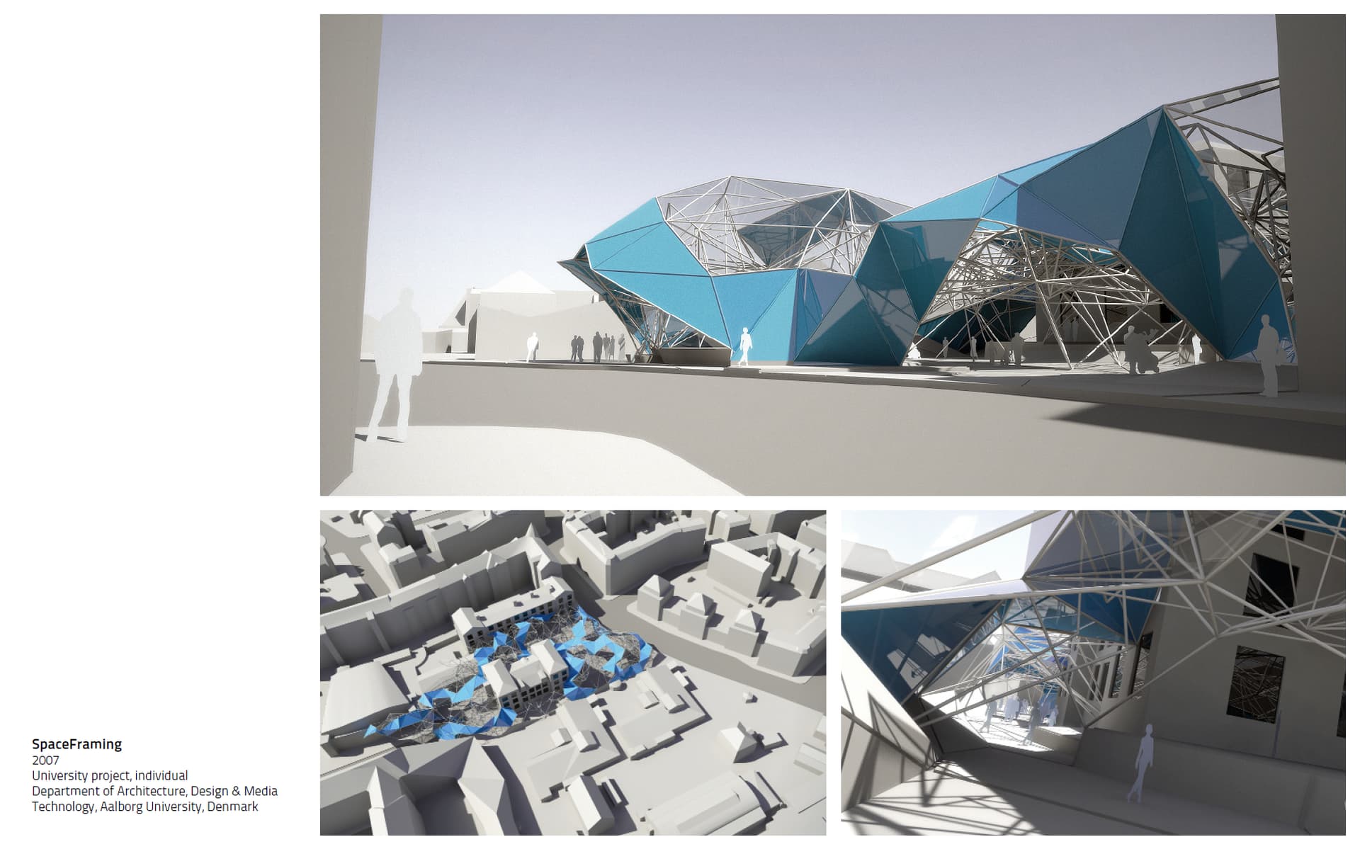


The geometry generation was quite close to what Peter describes:
-
Generate point distribution within site envelope. I used the Nucleus physics engine for this to repel particles and get an even distribution. One could use Kangaroo for this or maybe simply Populate3D.
-
Connect points by proximity and cull/add elements manually. This was done using a Maya MEL script.
-
Generate triangulated enclosure.This was also scripted in MEL script by first drawing one triangle and then searching closest points from this and doing basically mesh walks on a point cloud.
That is, not really informed by environmental or structural analysis information. Which I’d definitely be driving such design by today ![]()
Well … some day test Plan B : distort randomly (in x/y/z) 3DGrid pts. Impossible to tell that’s a “fake” result.
Here’s results using 2 rnd Pts Methods: the classic AND the distorted “ortho” 3d Grid way (a shift option every even (or odd) “layer” in Z may yield a better looking chaos).


But all that require a serious amount of interactive post processing most notably with regard rigidity (i.e. tetrahedra per 4 connected Nodes) and member clash issues (i.e. tubes, sleeves, cones etc etc) and panels clash issues (life sucks).
Meaning that … a manual design is always the way to go - by a million miles.