My surface looks smooth when it’s in SubD but when I thicken it it gets these weird divots. What is causing this?
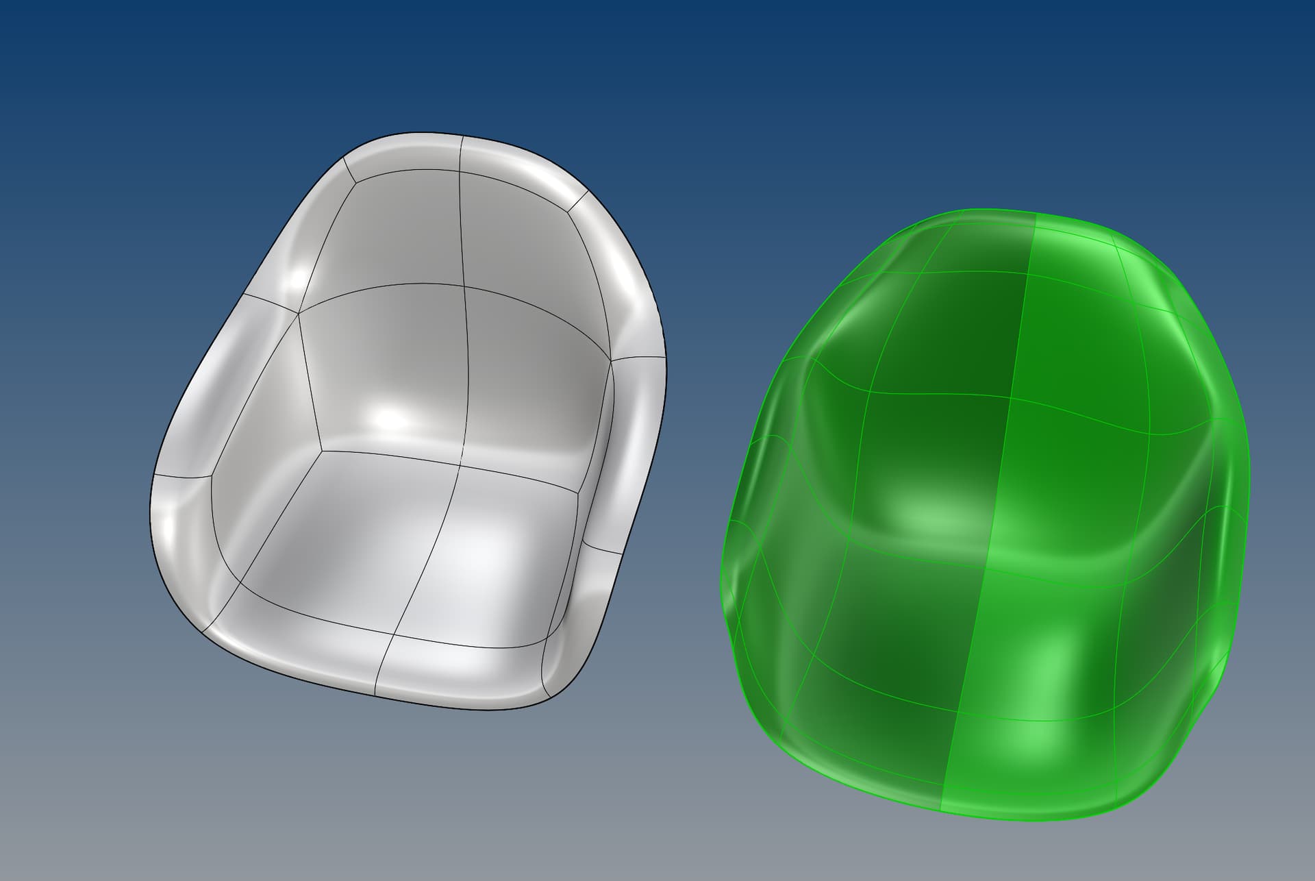
Right - SubD object, Left - OffsetSrf

Charles
Hi Charles - I can’t tell if tyou are offsetting outward or inward but in general the design surface, the one you care about most, most visible, etc should be what you model, and you can generally expect some ‘degradation’ on a literal offset of that. The alternative is to model both surfaces.
That said, post your file and someone will have a look.
-Pascal
Hi Pascal,
I guess I should’ve clarified, the bumps are appearing on both sides of the thickened object. Have a look:
Here’s my file: Chair.3dm - Google Drive
Thanks,
Charles
Hi Pascal,
That was one of my first thoughts but it doesn’t look like that’s the case… The visual artifact is showing up forward of where the 5 points connect.
Regardless, is modeling with 5 points together like that discouraged? My professor was doing it all last week and never mentioned that it could be a problem.
Charles
Seems like it is the conversion as Pascal mentions above. Maybe @pascal or @theoutside can explain when to use which continuity option for the extraordinary vertices.
In the screenshot below you see a simple model with star points. I’d say it is impossible to model it without star points / 5 edges on one vertex. The green object is converted with G0, the orange one with G2. Your object looks fine with G0.
Chair.3dm (5.3 MB)
PS: Your file size is only so large because of the mannequin… You could have uploaded directly without deviating to google drive.
Currently, the quality of the star points on the NURBS surfaces generated by the “toNurbs” command in Rhino 7 is not good. Here’s my solution:
Apply the “Subdivide” command to the Subd model, subdividing it 2-3 times.
Then use the “toNurbs” command to convert it.
Note:
After the conversion, the continuity quality of the star points on the NURBS surface improves, but the overall structure of the model becomes more complex compared to the original.
It is recommended to make a backup of the Subd model before subdivision for ease of modification in the future.
It depends on the continuity you choose doesn’t it?
What is the benefit of G2 vs G1 or G0?
see also here
and the help about “to nurbs”
Makes the polysurface G0 at the extraordinary vertices. The shape of the polysurface will be as close as possible to the SubD.
Makes the polysurface G1 at the extraordinary vertices. The polysurface deviates from the SubD a little bit more than G0.
Similar to the G1 option, but tries to make the edge normal deviation around extraordinary vertices 1 degree or less.
Makes the polysurface G2 at the extraordinary vertices.
Forcing G2 adds bulges or dents around extraordinary vertices.
Currently, no matter which continuity option is selected, the continuity of the star points(Extraordinary Vertices)after conversion is difficult to achieve to my satisfaction ![]()
@charlespick I’ll confirm what has been said here, these artifacts you are seeing come from the conversion of the SubD to NURBS and not from the thickening itself. This is a fundamental limitation of converting a SubD to NURBS and the only way to represent the SubD more faithfully is to increase the number of control points on the NURBS (converting after subdividing for example, or with the new G1xx option in ToNURBS in Rhino 8), or increase the degree of the NURBS (we do not do this).
These artifacts only show up for star points / extraordinary vertices, i.e. vertices that are not connected to exactly 4 smooth edges (or 1 smooth and 2 creased edges for boundary vertices); furthermore saddle points (extraordinary vertices where some edges go above the median plane, and some below) are especially prone to bad to NURBS conversions.
I get better results for the conversion using this new G1xx option in Rhino 8. You can either offset the SubD first (_OffsetSubD _Solid=_yes), then convert to NURBS (_ToNURBS _SubDOptions _ExtraordinaryVertex _G1xx), or in the opposite. Using the _OffsetSrf command on the SubD will convert it to a Brep with the default G1x option and prevent you from seeing these results.
https://docs.mcneel.com/rhino/8/help/en-us/index.htm#commands/tonurbs.htm#G1xx
If you are able to keep using a SubD model (or a mesh representation of the SubD), all the way through to production or rendering of your model, then these issues around star points do not matter much. If you need to export to NURBS at some point in your process, it is good to be aware of these issues for star points and reduce their number and place them at strategic locations where they won’t be in a saddle configuration and away from large interior smooth areas.
Chair_PEC_Rh7.3dm (8.9 MB)
@pierrec
Thanks for your work (G1xx)
and the post above
why ?
one nice approach would be to get a nice surface and for the final production refit the surfaces with degree 3 or 5 within production tolerances ?
did you compare the latest Rhino V8 G1xx results to Fusion360 or old T-spline ToNurbs results ?
@gustojunk mention in above, linked post that the results are better ;- (
(sorry - Currently I do not have a running T-splines nor Fusion360 installation…)
will equal edge-lengths in the control polygon increase starpoint-conversion-toNurbs quality ?
Are there any special cases for a 5-star-point (beside planar ![]() ) where the conversion is nice by default ?
) where the conversion is nice by default ?
thanks, kind regards -tom
![]()
Maybe I should have said “we do not do this in ToNURBS yet”. We wanted to first have a reliable degree 3 conversion with a controlled number of spans per face (1 span for most regular quad faces, progressively subdivided into up to 4 spans, and in N surfaces for N-sided faces, as you get closer to non-quad faces). This makes it easier to edit the resulting Brep.
Not sure I follow you here, do you mean that you’d use the G0 option in ToNURBS first, do something with the Brep, then run a special version of ToNURBS that would increase the degree to 5 and move the CVs of the Brep again to get closer to the SubD? In this scenario, why not just get the final version straight away?
Not with these two, but I know Siemens NX has a very conversion to NURBS which is both smooth (G2) and accurate (i.e. close to the limit surface of the SubD). However, they use degree 7 surfaces.
I don’t know, maybe, but nothing in the math we use to come up with the NURBS representation makes me think equal edge lengths would always result in nicer surfaces.
Not that I know of. The bad cases are the saddle points, and especially 6- and 8-valent saddle points. These just convert into a giant flat spot in the converted NURBS.
Hi Martin, are you saying that it is impossible to model this specific chair without star points? I’m still new to subdivision modeling so I think that’s what you’re saying, but I had never considered that forms are inherently restricted to a specific subd topology.
Hi Simon,
This appears to work. Thanks for the tip!
Charles
I converted the subd to nurbs using all of the options and it appears as if they all have some level of weirdness. I’d say G0 is the only usable one, but you say that is “as close as possible to the SubD.” What won’t be accurate in this case? Is it still a good representation of the design intent, for a visualization and/or manufacturing intent?
If I wanted a true understanding of this surface, even if it’s not perfectly accurate compared to the original subd, would it be a smart idea to rebuild all of it as a single surface instead of multiple joined surfaces? After all, for a design like this one, a single surface does make more logical sense in one perspective.
What does increasing the degree of the NURBS mean in this context and what do you mean by “we” do not do this?
My gut feeling has always been to stay with a mathematical representation of my work rather than using a mesh, which I guess is still mathematical but still not as flexible. It sounds like G1xx in 8 will solve this issue entirely though? Maybe SubD is just too young?
I’ve learned a lot reading through this thread so thanks to everyone who has chimed in. My apologies for the delay between replies as I’ve been very busy going to graduation ceremonies this week. ![]() If I were to take this project solely to visualization I think I would either follow Simon’s subdivision trick or use G0, at least until 8 comes out. I’m not sure what I should consider if I need to have something suitable for manufacturing however. If I need to export this to STEP to go back into solidworks for example, I would need to convert it to nurbs somehow. Should I rebuild it as one surface to be perfectly continuous? Should I just go with G0 because it looks right? I can’t detect any issues with zebra stripes so I guess it should look good injection molded or 3d printed?
If I were to take this project solely to visualization I think I would either follow Simon’s subdivision trick or use G0, at least until 8 comes out. I’m not sure what I should consider if I need to have something suitable for manufacturing however. If I need to export this to STEP to go back into solidworks for example, I would need to convert it to nurbs somehow. Should I rebuild it as one surface to be perfectly continuous? Should I just go with G0 because it looks right? I can’t detect any issues with zebra stripes so I guess it should look good injection molded or 3d printed?
You can get quite close to your original model with a full quad layout:
You can always drape a quad grid over an open manifold surface (with a boundary that is exactly one closed manifold curve); it’s only going to be a question of how many vertices you will need to approximate the shape well enough and how easy the SubD will be to edit and manipulate.
As @martinsiegrist showed, there are plenty of shapes where you need one or more star points in the topology.
G0 will be as close as possible to the SubD surface location (no weird bumps, points on the NURBS are close to points on the SubD), but it will be only G0 at the edges around a star point (i.e. continuous in position but not in tangents (would be G1) or curvature (would be G2) across an edge). A SubD is G2 everywhere except at star points, so the NURBS not being G2 is what will be an inaccurate representation of the SubD.
That’s one way to get a nicer NURBS conversion, yes. If you start from a rectangular grid as your SubD topology, you will get a single NURBS surface as output. Moving the extraordinary vertices to positions where there are not saddle points could help too.
Currently, the conversion of SubD to NURBS uses degree 3 surfaces only. It could use higher-degree surfaces for conversion that are both G2 and close to the SubD limit surface (no weird bumps). “We do not do this” meant that this higher-degree conversion is not implemented in Rhino (yet).
Have a look at the example file I posted above to see if G1xx works for you. It should be saved in Rhino 7 format. Or try the Rhino 8 WIP, it is accessible to anyone with a Rhino 7 license.
This is certainly possible but the sqewed faces create problems too, don’t they?