Hi
I’m really new to Rhino, but I’m out of ideas how to google my question:
If I sweep along a circular closed path, I run into 2 problems:
On export I end up with 2 half circles with an opening (invisible, because of duplicate vertices)
That wouldn’t be a problem directly, however the auto unwrapping creates a seam right where the two halves meet, which does create a problem for me.
This also happens, when I don’t close the ring, for some reason I cut on one side, but the other one gets a seam.
I also noticed that the geometry is irregular, if I extrude along a perfect circle I would expect all edge loops to be evenly spaced. However where those to pieces meet you can see 2 extra loops, ca. half the distance between the others. I found tutorials about this, but they all had the same phenomenon, but didn’t explain (notice?).
Can you post a 3dm with your curves and the resulting surface? Also, what file format are you exporting as and which program are you going to… I assume this is where you’re unwrapping the UVs.
Can you explain anything more about the intended workflow too and what you want versus what you’re getting? My guess is the problem is a seam in a texture map in another app when rendering. Is that correct?
Thanks for the quick reply guys.
Actually the models come from someone else, I’ll ask them how exactly they do that tomorrow. I just assumed they use the sweep tool, bc. that’s what I found in tutorials.
The end plan is: Take Rhino models, export them as .fbx, import them in Blender and refine them with a script. So everything needs to be very even. I can remove doubles, get the sharp edges back and end up with one piece, but the UVs remain broken. See image. Some even have flipped in xy.
It looks like it’s modeled in two pieces, I imagine due to modeling half and then mirroring the model. The texture map could be set to Cylinder in the Properties panel>Texture Mapping settings instead of a custom Unwrap as you show to get around the seam. Save as Obj and the mapping will transfer too as long as the appropriate option is checked in the export settings, same for FBX I believe as well.
If you still need help post the 3dm… I bet it could be kept together for a custom Unwrap too with a little editing.
They said they indeed use sweep1, but they did not mirror all rings. However the problem exists in all rings.
I think it all comes down to the uvs. Game engines don’t know seems, so if you want to cut UVs, you actually need to separate the vertices, I think that is what FBX does, I’m going to double check that though.
Regardless, I would need the UVs to be consistent, not divided and especially no gaps or even 90° rotation. They also come out with very different surface representation (scale). I don’t mind them overlapping btw. Ideal (but not necessary) would be if they were all centered.
I attached the 3dm. Note the smaller gaps betw. the edge loops at the opposite side of the diamond. In this version I was told there was no mirror used.
EDIT: Custom unwrap is not really an option, we are talking about 1000+ Rings, I need to be able to process them automatically.
EDIT: I just exported an .fbx with Blender, it does not split the model where the seams are, so that’s probably done individually by the GEs.
A custom unwrap object or a cylindrical projection would work on the model you uploaded to get rid of the obvious seam on the bottom of the shank. So it’s possible to edit the UVs in Rhino to prevent the texture breaks across seams in the polysurfaces but this won’t be an automated process to deal with the number of models you’re working with. There may be some automated UV tools out there that could help but I don’t know of any to suggest for this. You might need to do the UVs in Blender if that’s creating less seams due to it being meshes rather than polysurfaces. I don’t know if there’s an automated workflow there for this either though.
Cylindrical mapping means using orcro or generated coordinates for texture mapping inside Rhino, which would be lost on export, right? Or can you “apply” them in order to translate them into physical UVs?
The Rings get modelled by designers, so simple stuff could be handled by those. In Blender I would use the unwrap mode “Follow active quads” which unwraps an even surface following the geometry rather than bending it because the Ring is round.If I could just get Rhino not use that gap and and unwrap the same way it does now, but with the entire ring not just half of it, my problem would be solved.
Also could you tell me what causes the irregular distance between the edge loops at the side opposite of the opening? I’ve seen it occurring in tutorials as well.
Cylindrical mapping should export in obj so I expect fbx would work too.
Since Rhino is a surface modeler primarily and the ring is not modeled in meshes, the surface layout will control the default UVs. If the shank were one surface instead of two you wouldn’t have the issue once you go to meshes. [quote=“Frederik_Steinmetz, post:8, topic:44921”]
what causes the irregular distance between the edge loops at the side opposite of the opening?
[/quote]
Can you screenshot what you’re asking about here? Thanks.
As you can see the distance between 2 edge loops is not entirely consistent. Opposite of the diamond there are 2 extra loops. This is only a minor issue, filesize will be marginally larger, but it makes me a bit “nervous” since I usually use my own models and especially in game engines I am aiming at perfect geometry. Also it might have to do with the UV issue.
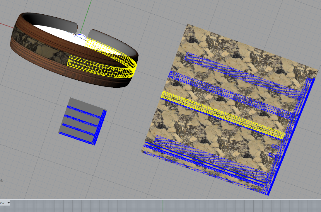
On the left you can see what UVs I get after I drew a cylinder around the ring (with the same orientation of course) and applied the mapping. It’s still split where the extra edge loops are and not right.
Your example looks like a custom unwrap where there weren’t enough seams selected so it could flatten logically.
The term edge loops applies more to polygonal modeling in my experience but I know what you mean. In NURBS modeling you’ll have closer isocurves at surface seams to establish continuity with the adjacent surface. This will affect texture mapping most if the default of by surface domain is used.
I know it doesn’t help much given that these are not your models but I’d try and model the shank in as few surfaces as possible to simplify seam selection. If we didn’t have the seam at the bottom, the isoscurves would be even there and the default surface domain mapping may have been adequate.
My cylindrical unwrap failed, because I didn’t uncheck capped… Now it’s working just like yours, a big step forward, but I still have one problem. The map you provided didn’t contain squares, but rectangles, but they were being displayed as squares. Ergo, the UVs don’t have the correct ratio.
I might be able to correct that manually, but I would be delighted if I could skip that. I guess manually adjusting the cylinder may be an option, but again, I’d prefer an automated version, any ideas?
The UVeditor can be any aspect ratio you drag out so I changed the tiling values for the texture in the material until they appeared square. The Length command can be used to measure the edges of the area we’re mapping and then those values can be used to make a rectangle that you can snap to when dragging out the UVeditor. This is the only way I know of to make the UV editor aspect ratio match that of the surfaces being mapped. The image texture itself is square while the surfaces being mapped are a long rectangle once flattened.
I don’t mean the aspect of the UV Editor.
On the texture You used the checkers aren’t square. But mapped onto the ring they are. If You map the test texture onto it, you will see the squares are stretched. Which means the x:y ratio of the UV island does not represent the surface’s x:y ratio. You can adjust it by manipulating the cylinder, but I was hoping there was a button for that.
I think that’s due to the cylinder mapping not knowing what the aspect ratio of the meshes for the surfaces are… try a custom unwrap instead without selecting any seams then open the UVeditor keeping it’s aspect ratio square with the Shift key. Is this what you were expecting?
I can’t reproduce your result, the UVs are diagonal. What I did: press Unwrap, press Enter, create UV editor.
I also tried chaining and apply, but same results.
I can’t tell exactly from your image, but it looks slightly irregular, the UVs are not in a straight line and don’t fit exactly on the Plane
I think I’m going to use cylindrical projection and eyeball it.
The file may have changed here or on your machine at this point, it might be diagonal due to a joined edge to one of the little bits up near the setting.
Yes, you’re right the unwrap is not a perfect rectangle due to the curvature of the polysurface and the way the unwrap works. The aspect ratio is preserved though versus cylindrical once opened in the UV editor.
OK, thank you very much for your help, I’m going to go with the cylindrical method it seems the most suitable, I can tolerate slight imperfections in ratio much more than irregularities in “straightness”.
I would call this thread solved.