Hi,
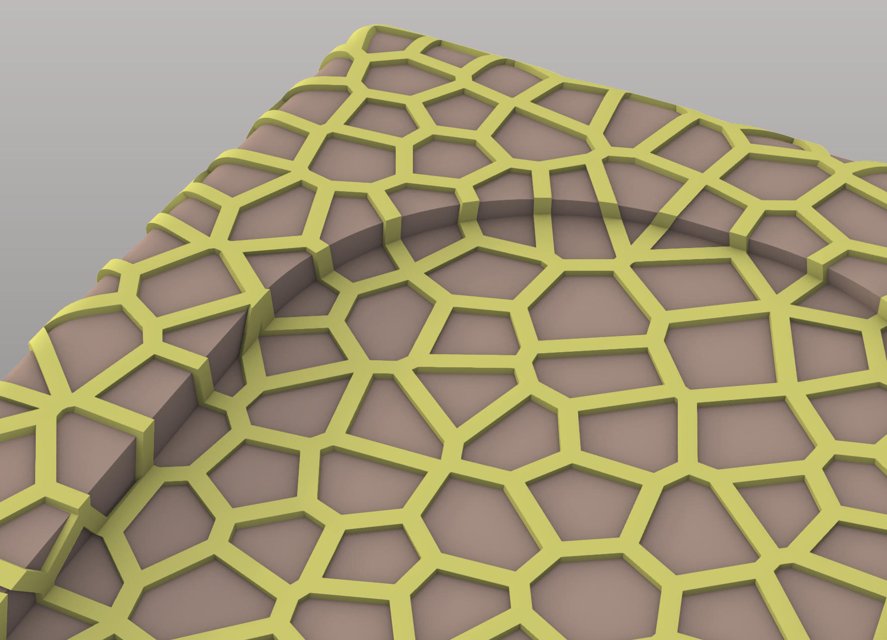
I have created plane voronoi cells extrusion on a source planar surface and want to map them to a surface that is simply connected (with a hole in the middle). I replicated the steps in several tutorials, but when I surface morph the cells onto this surface, the boundaries of the surface are not respected and the hole in the middle is also populated while it should not. You can see that in the screenshot below, the surface is in yellow (and symmetric about the clipping plane), and is on the inner side of the model.
While the pattern extending in the middle section is the biggest problem, I have remarked , by applying the workflow to other surfaces of the model as well, that the boundaries of the surface are never respected. The morph always extends rectangularly outside the surface.
I have tried to also create a 3D voronoi workflow but this creates other problems.
This is just a guess, but it looks like you have been caught on the obscure issue of “surface extents”. This means that if you create a surface, and then trim it in some way to reduce it’s size or change it’s shape, the real internal definition of the surface is NOT changed - only the displayed version is. So if you do something like a morph function on what you think is the trimmed/reduced surface that you see on screen, the morph results will actually happen to the original, unshrunk version.
I tweaked your GH file a bit to demonstrate this:
The (sort of) good news about this is there are routines that shrink the internal version of the surface definition down to what it appears like on screen. I remember someone here wrote a very short C script to do exactly that. There is a Rhino command that does it, which is what the C script calls - but I don’t use Rhino so I can’t tell you what the command is. I’m sure someone else here will add the missing detail - or correct me if I’m all wrong.
Hi Birk,
I thought that the surface may have been incorrectly represented in Rhino, but I simply imported it from a solidworks model. To be sure, I exported from solidworks only this surface. I do nothing on it (it says it is already trimmed). So I wonder if the problem is in the GH workflow, at one point maybe the domain is not correctly defined?
If I were a Rhino user I could probably be more help, but I’m not; I only use Rhino to display and export geometry I create with GH. Since you imported your geometry from Solidworks I guess there could be some question about what it’s precise internal form is in Rhino, but my sense is it would be converted (somehow) to Rhino’s standard Nurbs format. This would mean my initial response could be correct, and if so you just need to trim the Voronoi geometry to fit the curvy cutout space in the base geometry piece.
Elaborating on what @Birk_Binnard has already written. A trimmed surface has two parts: a surface that underlies everything that defines the geometric shape, and trimming curves that either trim away the outside portion of the surface or cut holes in its interior. The Surface Morph component operates on the underlying untrimmed surface. You can alter the U and V inputs to the Surface Morph component to change the extents of the underlying surface that is used to perform the morphing operation (this allows some scaling of the resulting geometry).
The geometry in your file can be used to construct “cutters” that can be used with split/trim/boolean operations to eliminate the portions of the Surface Morph result that you do not want.
Dear Kevin,
Thanks for you help.
I Think I understand what you are doing. You are lofting the outer and inner curves to create solid cutters, then trim the surface morph with them right? On the .3dm I upoaded my problem is that the extrusion is the wrong way (should go inward) and changing the surface morph W domain to -1 changes the solid cutter box but not the actual extrusion.
I order to better understand, I tried the grasshopper on a .3dm file that only contains the desired surface, but Trying to apply the workflow (changing the name of the layer in the pipeline to the one in the .3dm file) removes the surface and nothing else occurs. I understand that this has to do with the domain on search for surfaces in the first block, so I changed it, the surface appears but then not enough curves are detected to construct both inner and outer geometries. Could you help me? the idea is that I use this workflow on every surface of the enclosure as contained in the v1af4.3dm v1af3_voronoi.3dm (64.3 KB)
Join the surfaces from your source geometry. This creates 2 closed breps with normals facing outward.
Flip the brep representing the inside surface of your object so it’s normals face inward.
Merge the inner and outer breps to create a “Hollow Solid”.
Use this “Hollow Solid” to generate a 3D Voronoi.
Enlarge the boundary used to generate the Voronoi to elimate errors later with boolean operations.
Offset the voronoi cells inward to make cutters for solid boolean operations.
Subtract cutters from “Hollow Solid” created in step 3.
The whole operation takes a couple of minutes with 500 voronoi cells.
Some combinations of the number of voronoi cells and the offset value used cause errors in the boolean subtraction operation. In these cases, the method I’m using to do the boolean subtraction just returns an empty result with no information as to why.
I’ve included another method to do this boolean subtraction that will provide information about why it has failed but it is painfully slow (approx. 25 minutes with 500 voronoi cells). Could be useful if you wanted to determine why the boolean operation is failing but probably easier to just try different seed values for the voronoi generation and/or change the offset value until an error free result is produced. I’ve disabled this C# script component in the file I uploaded here.
This grasshopper file uses the Geometry Pipeline component to reference geometry from the Rhino file in your original post.
No plug-ins used, but uses a few relatively simple C# scripts.
Note: this file as saved takes a couple of minutes to get a solution. 3d_voroni_solid_diff.gh (18.4 KB)
Just one last question. I have trouble finding where in the GH workflow, to adjust the extrusion thickness, especially in real units (millimeters). I guess this is by setting where the surface intersects the 3D voronoi but I didn’t succeed in tweaking it.
3d_voroni_solid_diff_02.gh (18.1 KB) Note: Takes a couple of minutes after opening this file to get a solution.
Again, this file references geometry from the Rhino file in your first post.
I however have one additional question. In the 2D voronoi => surface morph workflow you can round the corners of the voronoi cells. But the option is not present for Voronoi3. I tried to fillet edges, but that fillets all edges, what I want is just the inner corners of the cells to have fillets for the CNC tool (it can’t machine straight angles).
What would be the block to use? Searching on google, I am afraid this is not so simple.
Do you intend to machine this in one piece or cut into multiple parts?
Your file contains 23 matching surfaces (one inner and one outer in each case → 46 total). Using a different voronoi pattern to generate each of these individual parts would produce objects having edges that don’t line up. What was your plan to assemble this?
It would be helpful to have a better understanding of what your ultimate goal is with this project.
As you can see the voronoi cells would serve as a core structure. The process would be like this: The outer shell is initially full, and cut along the middle plane (on the picture), then the inner material is removed. Aside from this, voronoi cells are CNC onto a smaller block that will be the inner shell. It is also cut in the middle and the inner material removed. So you end up with 4 parts: the two halves of the outer shell, and the two halves of the voronoi cells CNC from the inner sheel block.
On the model, I didn’t include the fixations yet. But as far as the question goes, the voronoi pattern would be CNC at once then cut in half. I would need 2mm radius for each cell corner.