Humble apologies in advance and as always that I’m probably asking something already answered and/or simply stupid. I’ve trawled pretty deep through the forums but can’t figure out how to do it, and have been banging my forehead to find a solution to this for too many hours now. I’m sure one of you brilliant people can point me to the obvious solution that totally escapes me.
I’m designing a structure that is hopefully to be built mainly out of CNC-milled wood. For cost/production reasons, we’re going with a Weaire-Phelan structure (meaning we only need to cut parts for two types of cells). The structure is generated through a bit of Octopusing and Bullanting; what I link to is probably not the final form, but a reasonable approximation.
The brep structure from Bullant is of course flawless. I now need to figure out a way of thickening the edges (or “wireframe”) of this brep to create mitred “struts” to be cut on the CNC. (I then need to figure out a way of placing boolean cylinders or similar for drilling bolt holes into those struts, but that’s a different story.) I’ve been experimenting with Weaverbird, Mesh+ and Cytoskeleton, but can’t seem to end up with the elements I need.
I’m linking to a file with six of the least unsuccessful attempts so far. (1) is trying to extract edge curves, but doesn’t work with Weaverbird. In (2) I separate out the 12-sided cells and get a good structure using wbFrame and wbThicken, but can’t separate (disjoint) the resulting meshes. (3) is an attempt to mesh the brep and then quadrangulate the mesh (so as to be used with Mesh+), but this still adds unnecessary “diagonals” (mesh edges) that I don’t want. Switching to a mesh-based approach to begin with, (4) was perhaps a silly attempt at using the wbCatmullClark tessellation but bring the number of subdividing iterations to 0 - doesn’t work. (5) is the Plankton/Cytoskeleton route, which seems to give me what I want but again ends up building meshes I can’t separate (and also adds diagonals as above). (6) Uses wbWindow and then Mesh+, which does give me separate meshes of the kind I’m after, but still with those pesky diagonals.
So. How do I either get my quadrangulated wireframe to behave without adding diagonals, and/or disjoint meshes produced by Weaverbird/Cytoskeleton?
It’s a pretty ancient thread, so the definitions might need some updating, but the approach I showed here should work for this:
The basic idea is insetting the boundary of each face in its plane, and also insetting the solid, then connecting it up with faces, so each edge in the original lattice becomes a 6 sided strut (since it comes from a foam lattice where every edge has 3 cells around it)
I’m actually also working on an update for cytoskeleton just recently - to make it work for general line networks, not just ones that come from mesh edges.
I’m sure you’ve solved it, as always. Had to leave my computer though, so couldn’t quite dig into your solution. I’ll get back on it tomorrow. GH flagged an issue with the clean tree component, surely on my side, which I do have (guess it’s a version issue of some sort). But then I still couldn’t disjoint (or similar) the mesh in your definition. I get very nice cells:
…but I need the struts/elements/sticks that make up those cells. Any ideas for how to get those?
I appreciate this is probably an impossibly stupid question, I just can’t get that in-between stage where I’m essentially “disjointing” or “ungrouping” the meshes (not exploding them into individual mesh faces). I really need to have a serious sit-down with myself and sort out my lack of knowledge when it comes to data trees (etc).
Can I just state for the record that it’s impossibly cool/amazing to get a response within minutes from someone who’s not just a genius but the actual co-author of the plugin. I asked for brilliant people, and got HS_Kim, Daniel Piker, and Michael Pryor – that’s like, I don’t know, Leonardo DaVinci, Michelangelo, and Raphael glancing over your shoulder and chipping in with a few friendly suggestions. I love the 21st century.
As I just wrote to HS_Kim above, I’m no longer in front of my computer, but will work my way though the 13 pages of ancient thread in the morning and see if I can figure it out.
Thanks a lot – and great to meet you again, if briefly, last year in Gothenburg.
Speaking of legendary threads, this classic, courtesy of the inimitable Peter Fotiadis, had me choke on my coffee the other day: Euclidean approach to mesh offsetting
Another approach is to just get the angles between faces for each edge and the angles between edges for each face to make each polyhedra then fasten them together…
This can be done using mesh topology (check ou tthe Sandbox plugin for example) This gives you the indices of the edges for each face and the indices of the adjacent faces etc.
You need the angle between each adjacent edge on each face and the angle between each adjacent face if you want to cut these mitre angles. You don’t necessarily need to model each strut… you need…
Length of strut
Mitre Angle at End1
Mitre Angle at End2
Mitre Angle along Outer joining edge.
(Optional Mitre angle along Inner Edge or leave 90degrees to face)
This shows angles between faces and angles between struts.
I made…
A jig to cut the struts to length with a plunge saw
A jig to hold the strut at an angle to cut the mitre on the long edge with plunge saw and Biscuit joint the long edge.
A jig to hold the struts so I could CNC machine the angles on the ends and finish the lengths
A jig to hold the 3 struts of a triangle together so I could dowel them.
If you work this out to create the 2 Weire Phelan Polyhedorns you could just bolt / dowel / glue them all together.
To work out each individual strut is going to be very complicated as the mitre angles will get insane where several struts meet.
The other way to make this on a CNC would be to make each face with angles cut along the edges, fix them together to make the polyhedra and then bolt / dowel / glue the polyhedra together. I was going to get V-Cutters made at the angles for each edge since there are not that many for some polyhedra.
Those elements look amazing - have you got a photo of the finished project? Would love to see them all put together.
Thank you so much for the instructive pointers. The last image of your mitred triangles is pretty much exactly what I had in mind, and your strategy is certainly an alternative and possibly better way forward. The bisquit joint idea is also perhaps/probably both more intelligent and neater than my bolt holes take; if you have a photo of the bisquit in action, as it were, that would be great to see too.
I’m in the fortunate position to be able to cut this on a Hundegger if it all works out, so there should be no need for jigs, which by the look of it should make this whole process easier.
That Hundegger machine looks incredible!
How do you program it? That might give you a clue as to what you need to output from your grasshopper model.
A biscuit joint is just a slot in two mating faces that you put a beech wood oval biscuit in. I bet the Hundegger can do that easily.
I’ll post some more images later. I didn’t go any further with my geodesic dome as this was just a proof of concept to see if I could make the pieces accurately enough.
By “I,” above, I mean “the guys at the sawmill who have and operate the Hundegger,” it’s not in my own backyard (yet). The machine runs its own software (I think it’s calle K2i) and while I thought there would be reasonably easy to feed it CAD files, it’s got its own file format (.bvn) and the (probably not entirely adventurous) machine operators prefer a “standard” cut sheet as a pdf or whatever, so that’s what I’ll get them.
But your comment about thinking how something gets cut on the machine was still helpful, as it made me reconsider part of my process so far. We’re about to build a prototype soon, and at least for that I think I’ll just trace the outlines of the elements and re-loft them. Since we only need a total of seven individual elements (including the bisquit joint), this is probably the quickest way to get something up and running.
It would still be interesting to understand if it’s possible to separate out connected meshes in GH (without resorting to exploding the mesh and either doing a silly amount of list item-ing or some nifty data tree-based culling that I’m not smart enough to understand); feels like I’m missing something incredibly obvious here. Might post a new question on that at a later date.
As was to be expected, coming from Mr Piker, this solution is precisely what I was after. Thank you.
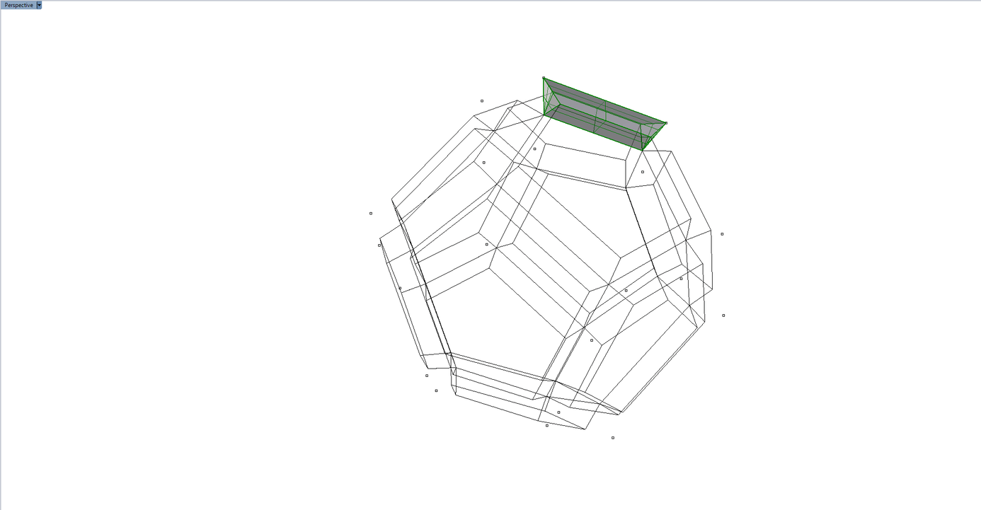
However, playing around with Daniel’s solution, I seem to be missing something when it comes to the culling at the end (which I probably too hastily removed); my mesh is now sort of open towards the outer shell of my initial geometry, like this:
I can then of course switch on the end points of my initial brep to understand between which points my final collection of meshes (or, even better, breps) should stretch: