Ok here’s the deal:
I want to create a freeform shell from a material with a thickness (e.g. polyurethane triangular cells). I’ve found many plugins that can create tesselations with planar cells on freeform surfaces(panelling tools, lunchbox, kangaroo) but so far I haven’t found a way to make a tesselation that meets the demands to create it from a fixed thickness material. I am willing to put in the effort to study in order to achieve the result that I want but
a) I don’t even know if it is mathematically possible (I would bet yes)
b) which tools I should invest in mastering.
I am explaining my objective more thoroughly in the following image.

Well …
The fastest way to deal with “thicken” some curvy thing (BrepFace etc) is to make a Mesh (say: using Mesh Machine) and then do the job. If the curvy thing is a collection of BrepFaces (polysurface in Rhino speak) then this approach is realistically speaking the only one.
This does the attached (works with any Mesh List) in 4 user controllable phases (variable: progress, try it and see what I mean) . Phase 4 yields a solid mesh (always in Mode2, in most of cases in Mode1 [ I must add some lines related with that matter]) There’s the usual bad news associated with replies of mine (the code only part) … but nobody’s perfect, he he.
TriMesh_thickenWithHoles_V1.3dm (160.4 KB)
TriMesh_thickenWithHoles_V1.gh (132.6 KB)
Note: If offset is set to real (as opposed to proportional) C# does some calculations and if the offset is not possible (or less that some user controlled values) displays the faces that are left with no holes (yellow).
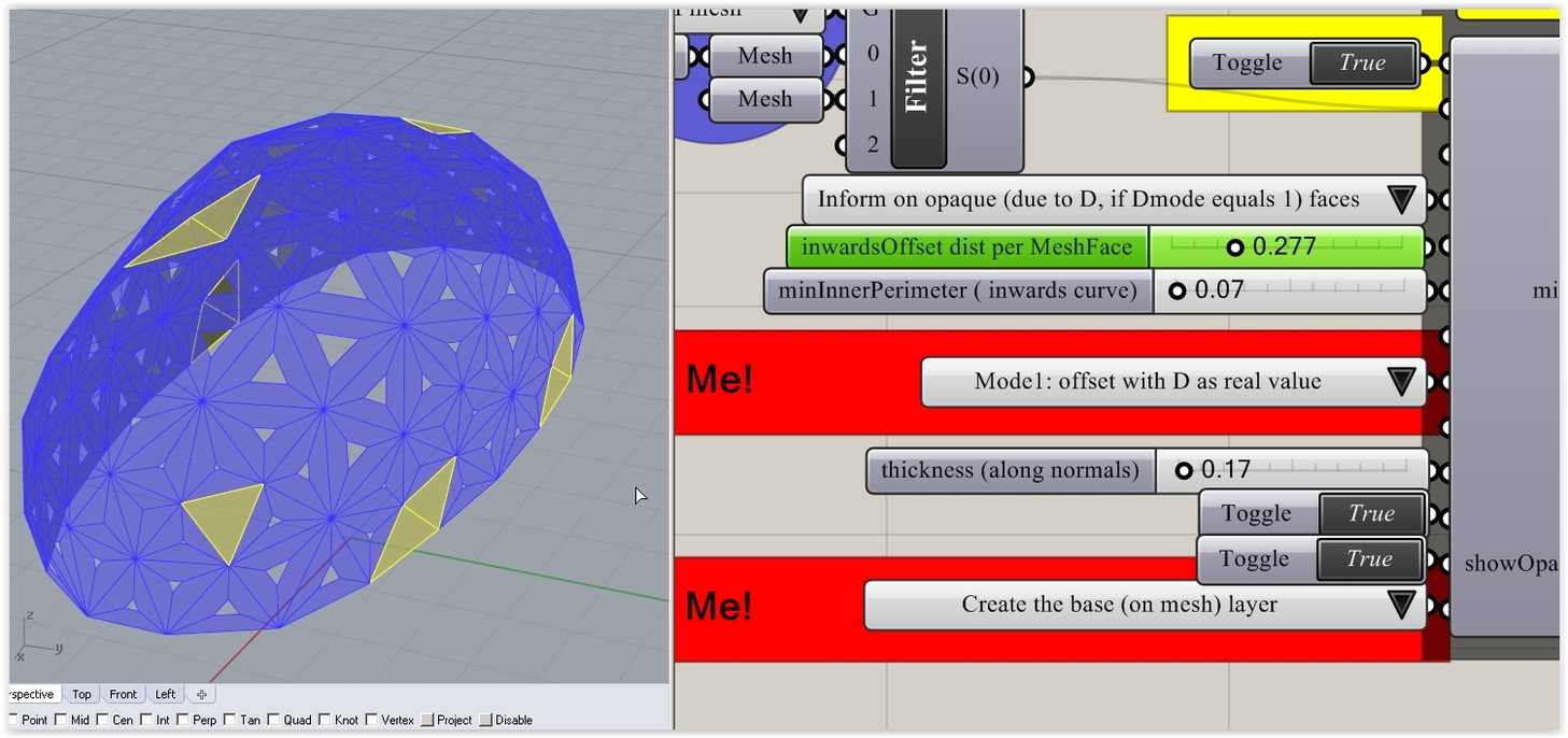
But the thing is that it uses mesh vertices Normals to do the job … meaning that the thickness per face (3 distinct pieces) varies slightly for more than obvious reasons. The good news are that the skin is smooth (no “gaps” from face to face). See what “gaps” mean in a similar case that I’ve posted recently (with Voronoi polylines):

Of course I could address the problem differently and achieve equal thickness pieces at the cost of a “rough” inner (or outer) skin But since you are after some toy model (Styrofoam or other) why bother? Who’s gonna notice it? And since 3d printing does everything these days (including food in some glitz(?) LA restaurants) why bother? And generally … why bother?
On the other hand … in real life … well … we don’t do things like these with that way in real life so why bother?
Note: if you are crazy about order on things use Times New Roman as Standard Fond (if Rhino crashes there’s other ways to do that by editing the Kernel xml file) other wise the C# and the parameters would end up in an ugly topological mess (I hate that):

Peter, thanks for responding, -also it is nice to see a fellow Greek (or of a Greek descent  )
)
But I seem not to have made myself clear: giving thickness is not a problem. the goal is to make something fabricable from polyourethane slubs (we are talking about a thickness of 50cm or so in order to be able to fabricate a pavilion by just cutting correctly the sides of big slubs.
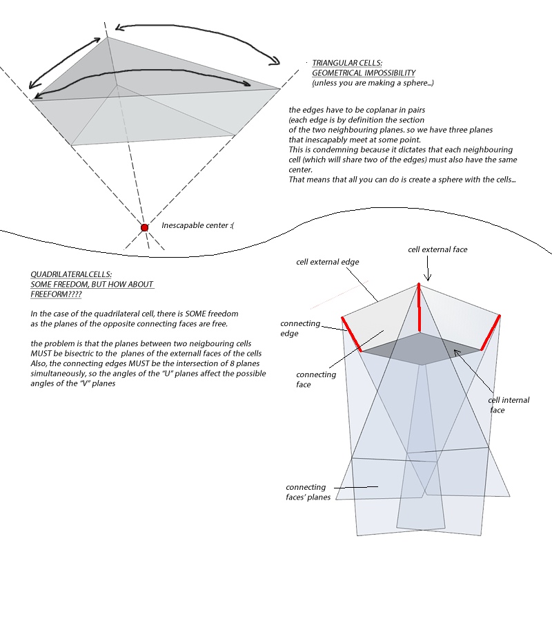
Nevertheless, by trying to explain my goal, I have come to understand it better myself. I’ve so far found that it really is impossible to achieve it with triangular cells (with the given restrictions all you can make is a sphere)
Now I am researching quadrilateral cells, that give a bigger freedom but still I am feeling that I’m trying to reinvent the wheel. I hope somebody who has delt with this issue could post something.
Well before things require a lot of Vodka > send me a PM in order to get back my phone (Greece) … and the rest would(?) become(?) easy(?).
BTW: Forget equal thickness et all. Forget smooth skin (or gaps) as well. The main issue is -like you said - “cutting correctly”. By what means can you achieve that? How to cut (manually) the sheets with the right angle (per face edge?). Or you want to cut them straight (90o) and fill the gaps with some thick Styrofoam adhesive? (like the one that we use in exterior insulating systems - Google STO systems). What about the very long curing time? Have you mastered anti gravity? Why spend time and effort for a Styrofoam (I assume rather big) toy thingy? Or this is a Trojan Horse for some Gunite concrete application on blobs?
Answers: The Lord, District 9, North Pole.
Plan B: Call me
You’re missing the point man, the whole point of this is to find what one can create using fixed thickness slubs.
If I find it can give versatile results I plan to construct a modified cutting machine. The idea is for it to be assembled like an igloo… So far I’ve made a few experiments with quadrilateral cells and it seems to be working (I did them in sketchup as I am not sure yet what conventions I should follow in my definitions so it is easier to experiment there by using intuition)
There’s a whole sub-field within Architectural Geometry that focuses on mesh offsetting under fabrication and aesthetic constraints. Helmut Pottmann and his work would be a great starting point here.
3 Likes
YES YES YES!!! that was all that I needed thank you very much!!!
1 Like
Really? Are you 100% sure? What if I haven’t?
Repeat with me: The point is to make things (WITHOUT stupid - or smart - restrictions) > justify their existence (the hard part) > make them in real-life > get the dollars and drive this:

Repeat with me: quads (or higher) in blobs (NOT “regular” stuff) is another rabbit hole. Reason? fabrication tolerances/complexity and VERY expensive real-life systems that guarantee that the skin doesn’t leak (in the long run). In the next call I can tell you some (very unpleasant) stories related with lot’s of WOW stuff out there … that … er … leak.
4 Likes
I’m with the bright side of the force! hahahaha
1 Like
We must arrange that meeting ASAP (you need Lord’s guidance into the eternal Darkness - the only Side is the Dark Side blah, blah).
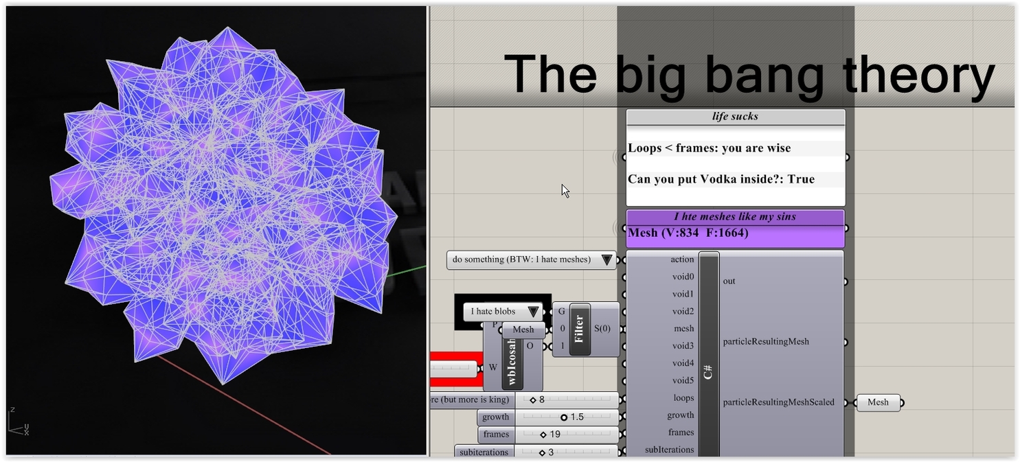
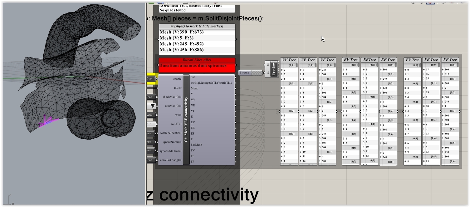
In the mean time I’ll mail you the thing promised (Includes: mesh connectivity trees (9 since we have vertices, edges and faces = 9 combos), face dihedrals, clash defection and most importantly what superbike/car to buy) AND the notorious BigBang case to test all the above … where big bang things happen (and then this, this and that):


BTW: Forms (and finding the Truth Out There) are OK(?) if you like that kind of stuff … but there’s the 1B question (in order to get the gist of what’s happening in the forthcoming material): Are you 100% familiar with connectivity trees? (lot’s of people they are not).
We have 3 sorts of animals in a mesh: V(ertices), E(dges) and F(aces). Exactly the same we have in Breps.
Due to that there’s 9 possible combos - meaning 9 trees… Enlarge this captured image (deals with Mesh Lists and NOT a single Mesh) and enjoy 9 freaky Trees with indices (but what they mean? You tell me). Are you OK with similar stuff? (not to mention DataTrees in general).
Peter, I am familiar with data trees (although from what I see, to a much - much lower degree than you) and I go from brickwall to brickwall, nevertheless its the mathematical clarity in these forms that I’m looking for. Once you have that you usually can find a way to translate it to machine language.
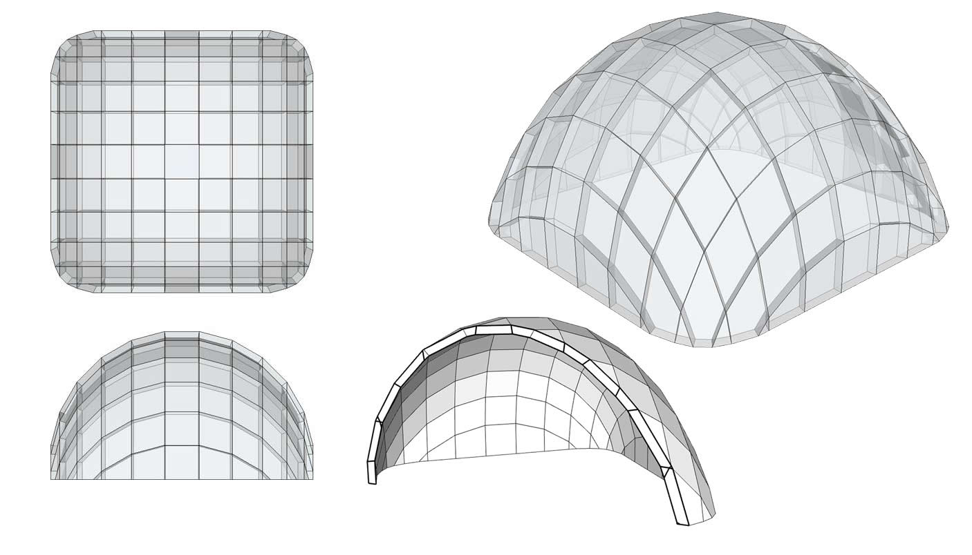
Anyway I’m continuing with my baby steps! I’ve managed to create this basic 9 cell fixed thickness shell and it has given me some insight into how the knots behave. Now I’m searching how the transformations ‘flow’ from one cell to another. (that’s the biggest challenge from what I see)
who knows what I’ll come up with… maybe nothing. But at least when you catch too many boots you learn not to go fishing at that spot again!

BTW: Only the Lord (the Merciless) knows the ideal spots for fishing where waters are dark, agitated and no fish is around (killing for fun other Eco-system members is NOT allowed by The Lord (but you are free to kill humans, or encouraged to do it]).
I’ll post later the dihedrals thingy (3 dimensions Tree: first = index of mesh in mesh List, 2nd = index of face, 3rd = index of adjacent edge (or face: - that’s a user option). In order to use it you MUST be 110% capable to manage anything in trees with many dimensions.
In the mean time:
- A mesh normal is the aggregate of the unitized edge directions (where edge the adjacent to any given vertex - that’s a classic VE/VV connectivity).
- A mesh faceNormal on the other hand is … er … the obvious. The related connectivity tree is EXACTLY like a FF Tree, so we use that for Normal connectivity.
- For a given faceNormal we loop into the adjacent faces Normals (FF connectivity) AND we find the common edge as well (that requires List intersections). That &^&^ edge is critical (see below).
- Imagine a plane defined at edge.PointAt(0.5) with direction edge.Direction. That defines a zDir. But where the plane is heading? That’s the 1M question.
- We compute the cross product (face Normal, adjacent Face Normal). If the dot product of that with zDir is < 0 we flip the plane. Google time (I suspect): cross/dot products and other freaky similar stuff.
- We compute the dihedral: double angle = Vector3d.VectorAngle(faceNormal, adjFaceNormal, plane); Calculation complies to the right hand rule and thus …I do hope that you get the gist of step 5.
Now if you do some sketches having all these in mind you can easily understand what’s happening. For instance: what’s the difference between convex/concave face/face topologies?
Of course you can thicken any mesh (tri mesh, avoid quads) and get pieces with equal thickness … but how exactly to do it? what means projecting a point in a plane? how to manage clash situations? (remember: ANY mesh). how to cut the pieces with variable dihedrals? (making auto layouts, that is for orthodox CNC) and most importantly what about the espresso/cigars required?
Answers: The Lord, District 9, North Pole.
In the mean time: the lesson of the day: what is planarity? is a chimera? is it just (note: I’m speaking for AEC stuff) another idea/trend like an I-Pad with 66 cores? can you do it in real-life AND not spend a gazillion of dollars without any reason? what I.M.Pei had to say about all this contemporary blob fever? what about form follows function?
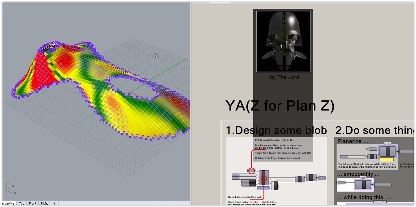
Get this ancient Kangaroo2 thingy (newer K2 builds may require replacing the solver) and answer all your questions at once. Of course I have it in a far more modernized version (only one C# , less is more) but … well… ancient things are always better than modern things.
YAZ_kinda_demo_V1.3dm (172.0 KB)
YAZ_kinda_demo_V2A.gh (145.6 KB)
Very impressive stuff! I’m glad I made this post! I spent most of my night yesterday educating myself about vertex/edge/plane offseting! nevertheless most of the papers I found are focused on approximation and/or fixed width beams.
So far I haven’t found a study with the attributes I’m looking for (not how you can make any surface this way but rather WHAT surfaces CAN be produced this way)
I am aware that many of my preconceptions are wrong. but that’s the process of learning, killing your misconceptions one by one…
Also Peter, you keep talking to me about approximating planarity… I am asking what you can do IF you take planarity as a given. Which are the attributes of the surfaces that can be constructed this way… (Not by approximation but in the strict, Platonic sense) I’m still in the process of reading all these books I’ve found. Once I understand I will post whatever I find to save any other newbies like me from their misconceptions!
Get this (no cross/dot stuff implemented on purpose) and think: what could be the algorithm in order to find the right dihedral? (play with the flip stuff as well). Meaning: how we could declare a face/face relation as convex/concave? (in relation to what?).
Mesh_dihedrals_DemoEntryLevel_V1.gh (119.3 KB)
BTW: Planarity (quads and higher) is a given only in Planet Utopia (and/or Zorg). Don’t been trapped in that rabbit hole (many entries, no exit). In the V2 of the attached def we’ll see some stuff on that matter.
BTW: You may wonder why I use C# in most of my replies whilst you don’t know that thing. Well … the reason is that the 99% remaining for doing some real-life stuff (after the diherdal part [1%]) i.e. how to interactively modify “topics” (vertices) on your blob (any blob) in order to avoid clash situations (and how to keep track on everything that you have done)…
BTW: There’s no truth out there. Everything is fabricated either by you (bad) or others (worst).
Task for the w/e (forget the offset mesh: too easy, get the long way home):
Alias T for Thickness.
- Create a very simple open mesh.
- Create the VF connectivity tree (Vertex to Face).
- Compute the normals (aggregate … blah, blah).
- Get the vertices
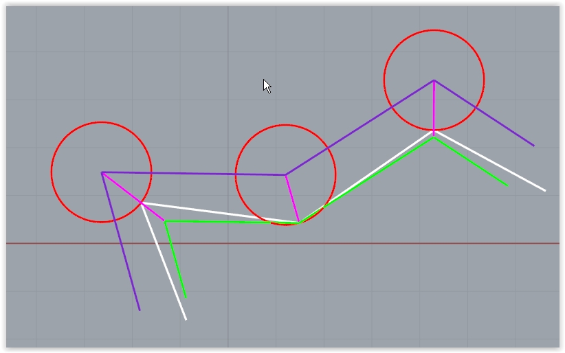
5a. Unitize each normal and multiply by T. Move vertices (4) - vertex + vector - and make the offset face. That does the thicken def that I’ve posted already here. The white line in the sketch.
5b. Let’s talk about the green line: for each vertex get the adjacent faces (via VF as in 2) and find the intersection of a line (from vertex and direction the normal) VS an offset mesh face plane (T) . Compare the ccx points. Are equal ? (within tolerance). If they are why we are talking about face/face dihedrals? Because they describe the taper angle, that is. If is too small … it’s realistically impossible to do any piece in real-life .
See this simple sketch (some abstract section) for distinguishing 5a from 5b
In the mean time found 10 more minutes for some changes on the ticken tri mesh List thingy
TriMesh_thickenWithHoles_V2.3dm (245.1 KB)
TriMesh_thickenWithHoles_V2.gh (136.8 KB)

- result: controls if one mesh or pieces are made
- tMode: controls if equal thickness things are made (base to top: planar, distance T)…
-
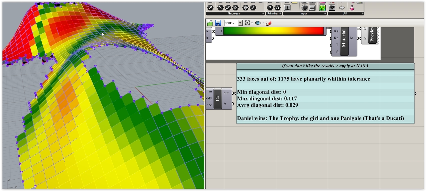
Planarity Check: gets the diagonals per face and per tapered sides (if result = pieces) and performs the classic planarity check (min diag distance) according the planarTol value (remember: we are not in MIT, we are sharks after dollars). For instance see this check on the demo data:
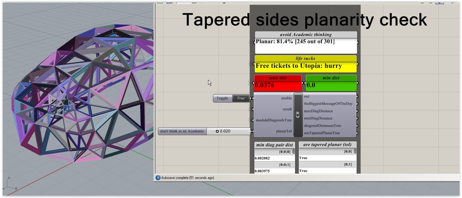
Now … if for that random (not relaxed via MeshMachine) blob thing 80% of the pieces have planar tapered sides (within 2 cm tolerance = absolutely nothing in big things [no glass] and real-life) … should you spend your time chasing chimeras AND the truth out there ? Not in a billion years (otherwise apply at MIT ASAP).
Even If I geared K2 for some simulation/“relaxation” on that matter (not that difficult, in fact I have stuff that does that but is rather slow) it could be 100% Academic since the main issue here is that you can’t do the tapered task by hand … meaning that if CNC/3D printing is on duty … why bother talking in the first place???
Moral: Life’s short, abandon ship, do some WOW stuff (and get the dollars).
In the mean time let’s play with some strictly internal stuff (not for public eyes, that is).
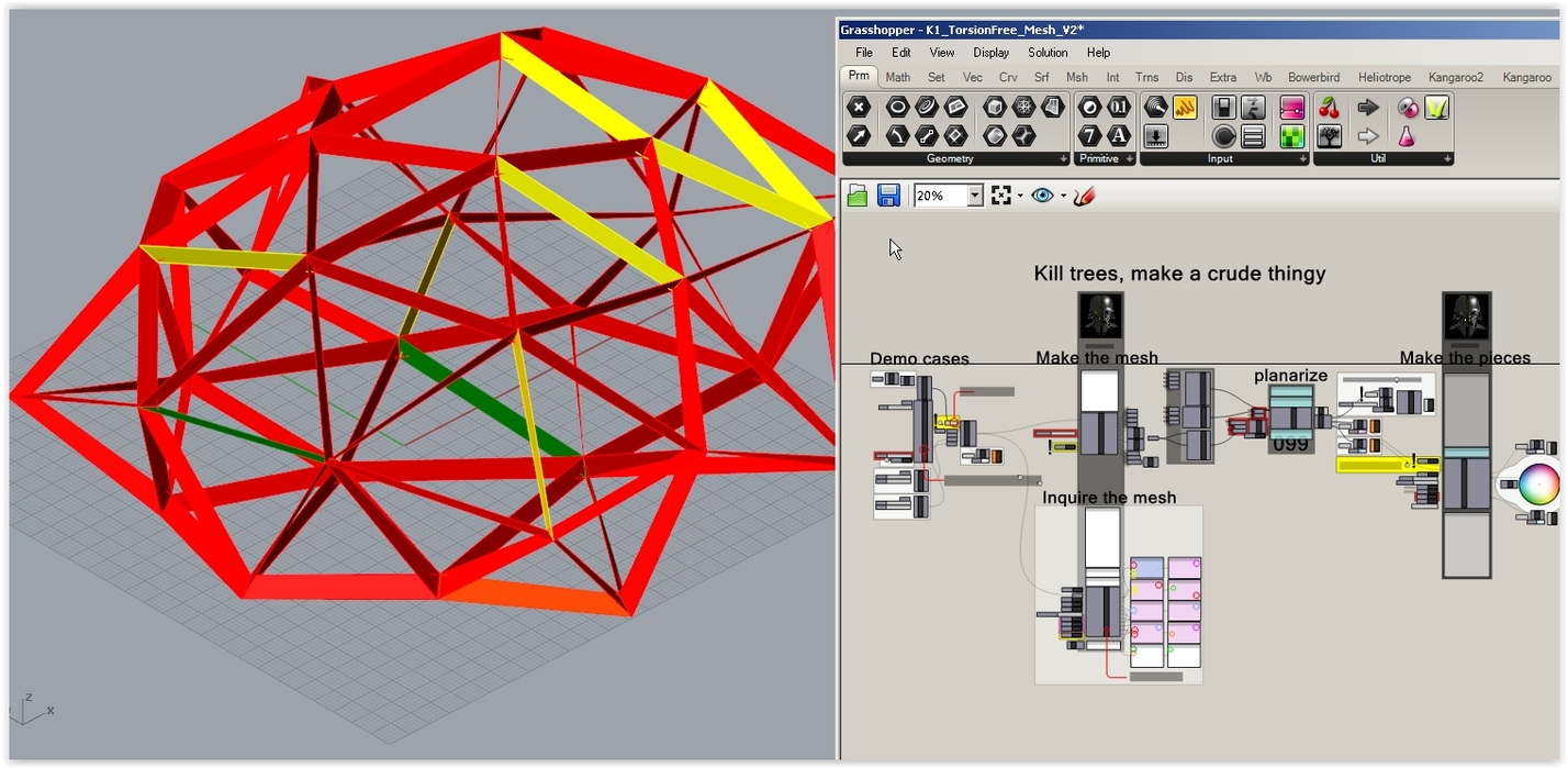
See this? Reds are not planar tapered sides (base/top faces are not on display for clarity):
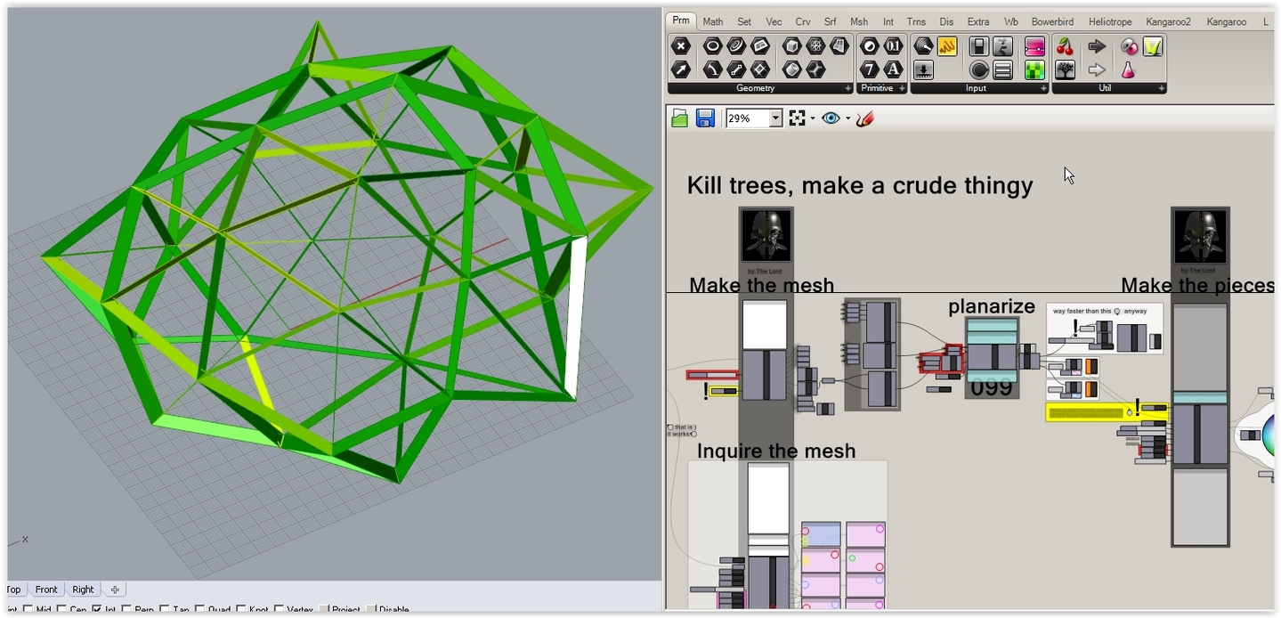
See that? Greens are planar tapered sides. How this is made? Who knows? (and who cares?). He he:
And some other stuff as well (production layouts and some detail [plywood frames]):

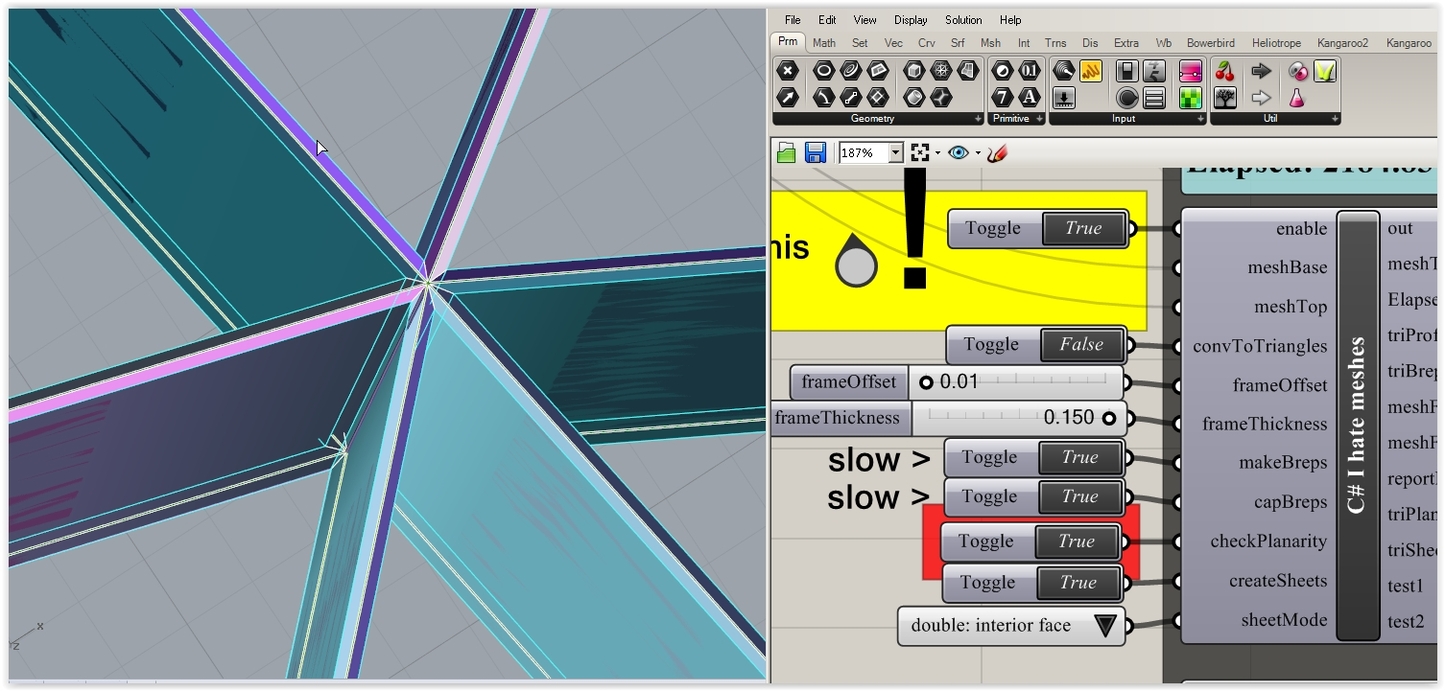
And doing a production layout without the planar fix part (non planar stuff is rejected).
