Still relatively new to Rhino + Grasshopper, but I have managed to succeed with some applications such as extracting data from public registries and reconstructing geometry for energy performance calculations. It has worked better than expected.
Now we are in the middle of developing a building configurator for different apartment building types. Namely, we have studied the Estonian national building stock and divided buildings by geometry and structures into different types. With each class, we have associated some corresponding values necessary for making energy calculations. Now, as we have building classes, which are very standardized, we would like to develop configurations for these buildings.
I am currently studying different strategies and alternatives for creating such configurations. Creating a base structure for buildings with ground, floors and roof surfaces is relatively easy. However, I can not figure out what would be the best way to go for attaching rectangular very standardized wall panels to the facade. Each apartment building has around 5 to 6 wall element types. The picture below shows these standard solutions for the two different regions of Estonia.
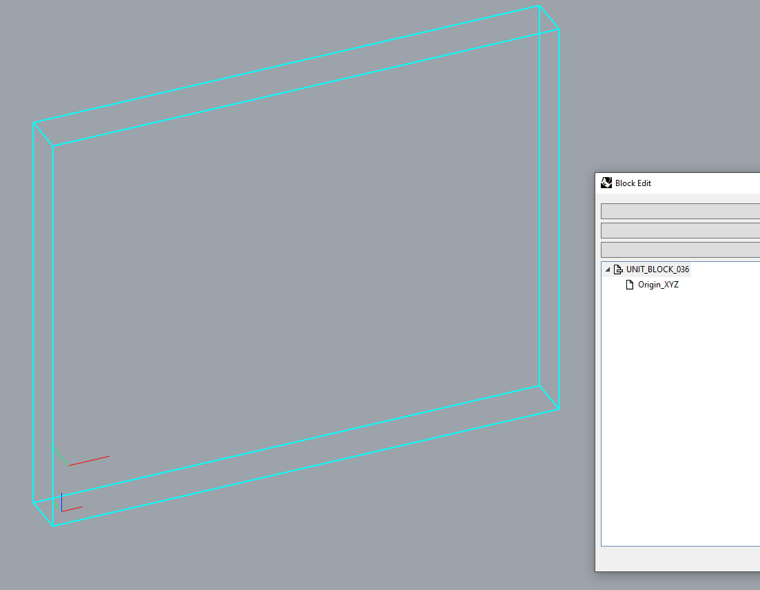
Using Rhino’s blocks. But I have understood that this a quite problematic and blocks are not adaptive!?
As I know Revit, using Rhino.Inside.Revit for driving placing Revit’s adaptive elements on the facade.
Now the questions:
What would be the best strategy to go and why?
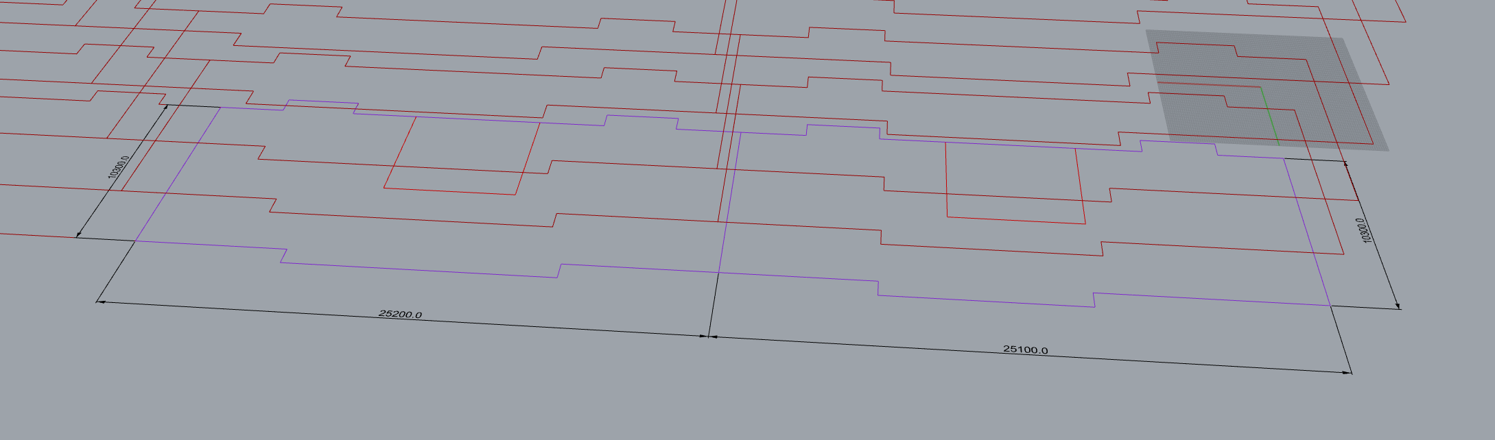
In either case, I need to define quads with points to add Rhino’s blocks or Revit’s adaptive elements, I guess. Different segments of the facade of those buildings have different wall panel types. Later, for deciding which block or element type to use, should I already divide base curve (purple in the picture below) into segments and include this information in these curves somehow?
Thank you @Japhy for a quick response. In the first order, the idea is to replicate existing buildings with existing conditions. That is, generate a geometry based on our existing knowledge of these buildings and enrich this with building typology data from our database.
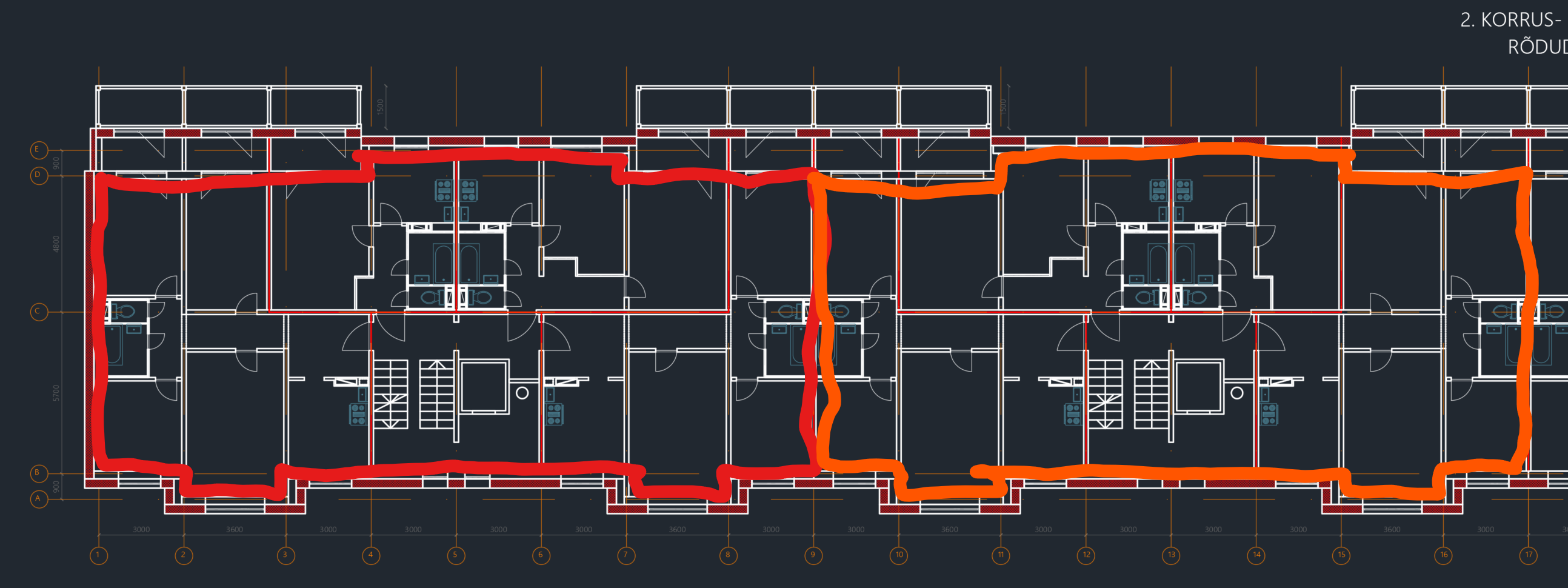
Regarding starting information, I have started with the interior curves of a floor plan. Red in the picture below is the building end module and orange is the middle module of the building. We have all the project documents and information about this structure, including wall types. For generating the base structure, I use the number of stairhalls, the number of floors, floor height, and plinth height. I could potentially divide the base curves into segments based on the external wall type. However, not entirely sure whether this is a good approach.
Yes, we have DWG drawings, Elevations and Sections.
The Red and Oragane represent the most basic units. Buildings with two stairhalls have the Red module mirror to get one floor interior curve. Buildings with more than 2 stairhalls have Orange modules in the middle. For example, if the building has 6 stairhalls, then the first module is Red, another four are Orange and the last one is Red mirrored to the end. This only gives the basic layout and if multiplied by the number of floors and their height you get the base structure for the entire building.
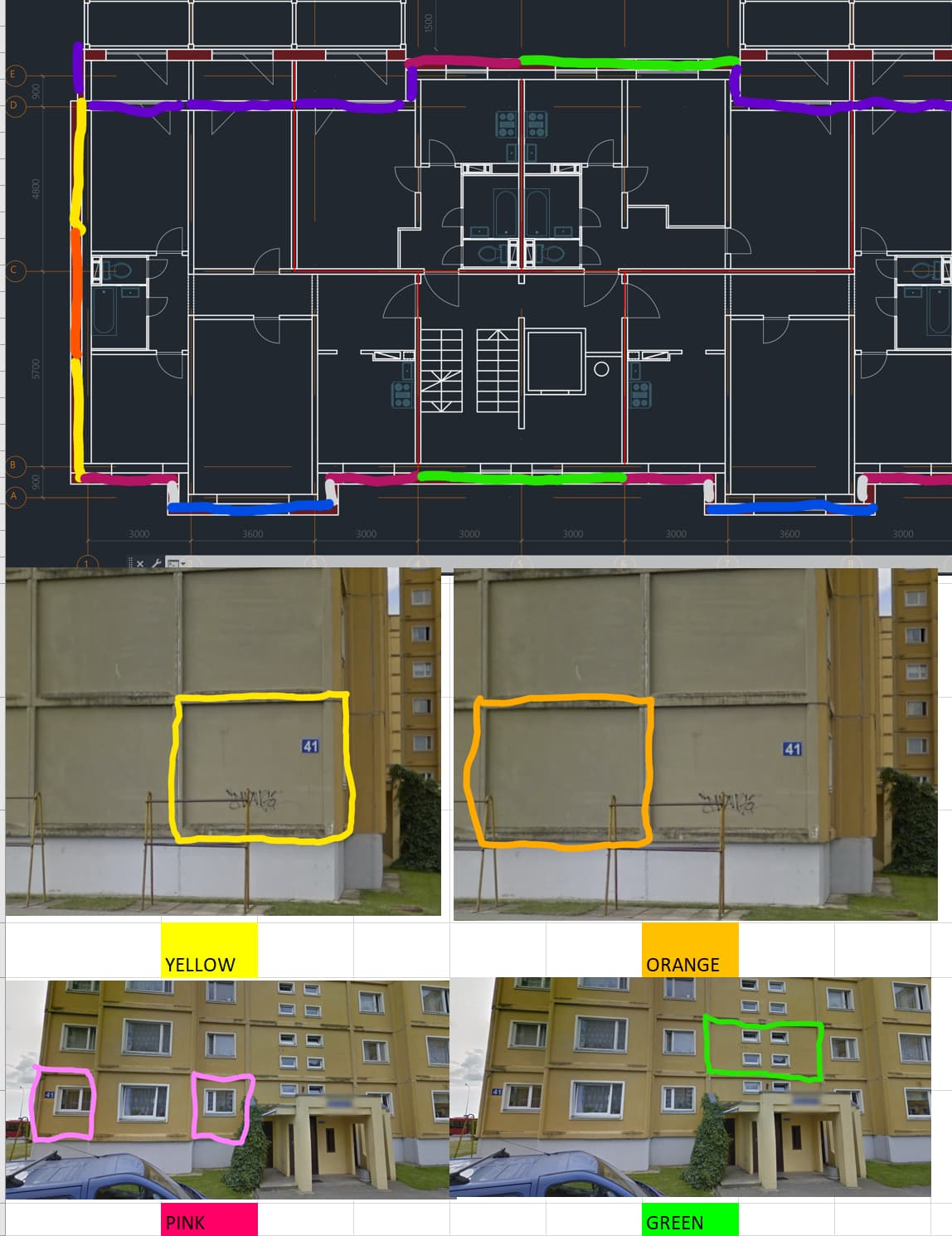
The next task would be to somehow decide which wall type and where should be attached. These depend on the segment of the wall, I mean where they belong. Here is an example of different types of panels in different parts of the external wall and so on.
I guess the question is whether this knowledge of different types of panels and where they go, should be already somehow defined with the original Red and Orange module curves or not? If so, what would be the proper approach?
Fortunately, the apartment buildings we are interested in are very standardized, that is, they are mostly shoeboxes. Hence, at the level of a building, only the number of stairhalls, the number of floors and the roof type are variables.
In the first order, yes the wall type is the main criterion. These are differentiated by the base shape. Another difference is whether these include windows or not, if they do, then which type of a window or windows?
I am not sure I understand what mate lines mean. Do you mean adjacent lines? If yes, then this exactly was the question.
Here is the temporary link to DWG-s for schematic design: Sign in to your account We have more but maybe this is enough for the beginning?
You can then use that info to distribute your geometry, managing everything via the usertexts vs putting it into a block. The block is instantiated but parts ect are only in the one place, unless need be.