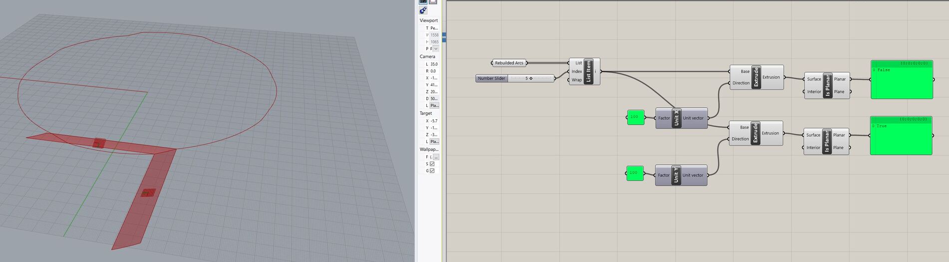
You can see individual arcs, connected to a perfect circle from the top view. All arcs are planar! When I am trying to extrude them along x- an y-direction, I receive different test results in case of planarity. It would be very good to receive planar surfaces in both directions, but I could not find any clean way to solve this.
I need at the end planar lofts like here:
An arc may well be planar, but that doesn’t mean that an extrusion of an arc must also be. If the extrusion vector is not within the arc plane, you’ll end up with a non-planar result. A cylinder for example is the extrusion of an arc, and a cylinder is not planar.
This means that there can not be a mathematically correct planar lofted surface between the corresponding arc pairs like I showed in my last screenshot inside the question post?
Correct, the line connecting your arcs is not in the plane of either of them. The arcs themselves are not co-planar either. And they’re not even mirrored, one of them is notably flatter than the other. You may be able to create a developable surface or some other kind of surface with zero intrinsic curvature, but not a planar one.
But I think that there is a little opposition: When you look at my first posted picture you can see that I extruded the arc along x an y direction. The extrusion along y direction is planar, but according to your statement, the extrusion only can be planar when created inside the plane from the arc. When you look at the extracted plane of the example arc it does not look oriented to the y direction. Do you know what I mean?
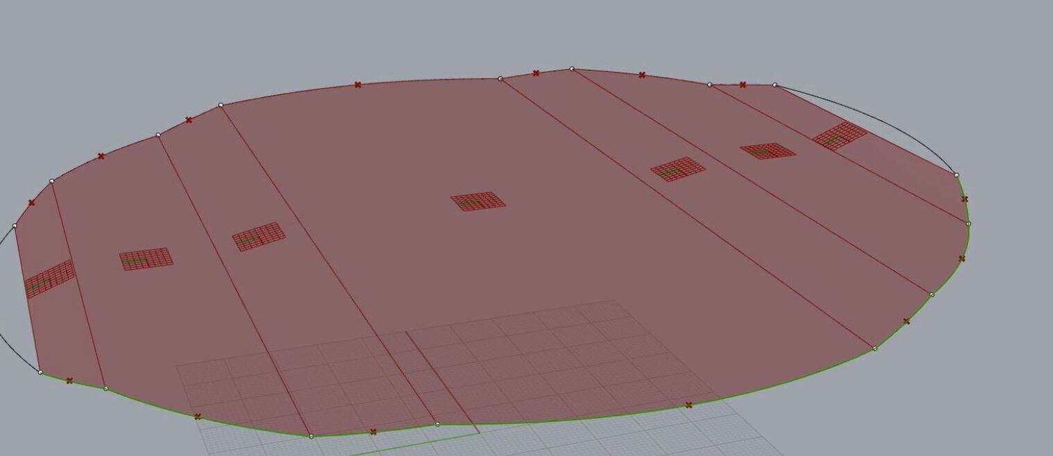
moreover it is strange, that I can achieve planar surfaces, when lofting between some arcs. but just the first and the last stripe is not planar. I do not see any logic at the moment
Joseph, I am able to see your solutions, but the strange thing is, that the planar loft is working for many arcs. There are only two stripes at start and end that are not planar. Because all arcs are created the same way. The error must be somewhere else.
It sounds like you just want to have a bunch of planes which are cut off by a cylinder or sphere. The arcs just seem to be a halfway point in this process. When you intersect a cylinder with an angled plane, the intersection is not a circular arc, it’s an elliptic arc. If you then force this intersection to become a circular arc you will introduce a measure of deformation which, when big enough, starts messing with planarity tolerances.
The distances from the end points to a “common plane” (Plane Fit) are so small that they appear as zero in a text panel, unless the values are formatted. Some of the distances from curve control points to that “common plane” are larger.