Did you open the exportes STP in Solidworks, Creo or any other program before saving it again?
Because this is a typical modification that other programs do when they update geometry internally.
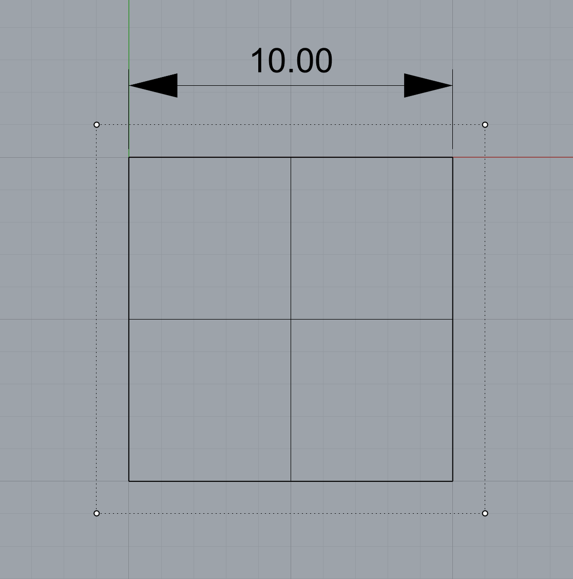
I noticed this behavior when exporting similar not trimmed flat plane (10x10mm) from SolidWorks to STEP file. When imported in Rhino7 (Win10) the surface is trimmed.
Would appreciate any information about why is this happening, and if there’s a way to avoid this behavior (exporting untrimmed surfaces as trimmed) while exporting from SW to STEP for later use in Rhino.
That sounds like a question that should be asked on a SolidWorks forum?
I’m not sure what the fundamental problem is that you are trying to solve. As you noted, you can turn that option on to change the behavior. That option was added in Rhino 5 to work around problems in other applications that read STEP files from Rhino and had issues with trimming.
If your workflow is .3dm → .stp → .3dm then you can either user that option, or shrink surfaces when you import the .stp file.
-wim
You are right, my goal is to build a workflow that will allow me to pass geometry from Rhino to Solidworks and back using stp format. And i’m trying understand if its possible without affecting the geometry.
I’m trying to understand other Rhino users experience, but thanks for your idea about asking this question on SW forum, also.
From your words and my initial experience i understand that different applications read stp files a bit differently. Do you know what is the reason for such different behavior in the context of STEP format?
I can only speculate. Ambiguous format description? Sloppy programming? Both? None of those? I can’t see how the answer to the question will help anyone. The fact is that different applications read files differently. The Rhino STEP importer and exporter has been fine turned over the course of more than 25 years to make it as compatible with other applications as possible.
-wim
The difference in the import is partly due to the surface type that is created in the STEP file. STEP PLANE surfaces import into Rhino as oversized Plane surfaces, while some STEP B_SPLINE_SURFACE_WITH_KNOTS import as untrimmed Plane surfaces.
To witness how fragile maintaining the untrimmed surface using only Rhino can be:
Create a planar surface using _SrfPt with a 4-point non-rectangular border, e.g.,
_What reports #4 as being a “trimmed surface. Plane Surface”
Instead of maintaining the underlying geometry, it is usually more important that a translation’s resultant B-rep face and edge shapes and vertex locations are within a tolerance to those of the starting B-reps. This is true for the examples in this thread.
Thanks for your in-depth explanation and examples, Steven.
From your description, it looks like handling surfaces using STEP format is not so straight forward as vertexes/primitives/normals in polygonal formats like OBJ. If I understand you correctly, differences in description of native (Rhino, SW, Creo) surfaces and STEP entities is the main reason why all these issues happen.
You mentioned the importance of keeping track of shapes and vertex locations tolerance. What is actually happening with the tolerance during export/import?
Would be great to know your approach for handling tolerance. Are there any tools for this in Rhino, or is it manual work?
In the case of a planar face, it would be an issue if you require it be an untrimmed surface and/or a specific surface type.
Differences in available surfaces types in each CAD application and STEP format, the choices of the application developers of which surface type to use, and other simplifications, e.g., face merging, affect the translations.
On export, the CAD application hopefully states the model tolerance(s) in the STEP file. Rhino does.
On import, the CAD application may use or ignore the tolerance(s) stated in the STEP file. Rhino uses it.
_StepUnitsAndTolerance states the units and tolerance that Rhino will use when importing the STEP file. If the file is opened, the unit of the Rhino file will match the stated unit. If the file is imported, Rhino will still apply the stated unit and tolerances before optionally scaling the geometry to the Rhino document’s unit. The Rhino document’s tolerances are ignored during import.
If the STEP file’s tolerance are causing problems when importing into Rhino, you can try _testSTEPImportToleranceOverride to set the importing tolerance. Set it relative to the STEP file’s units, regardless of the unit of the Rhino document.
Appreciate your explanations of the tolerance behavior in STEP and Rhino, Steven.
So, if Rhino is stating tolerance in STEP file, does that automatically mean that the geometry (B-rep face and edge shapes and vertex locations) from STEP file that is imported back to Rhino (or just opened) is within the tolerance as initial geometry?
Do you know if there is a way to compare tolerance of initial and imported geometry (B-rep face and edge shapes and vertex locations) itself, not just a tolerance of the STEP file?
As far as I can tell, the stated tolerance in a step file is a meaningless number.
It does not mean that edges are within that tolerance. It does not mean anything.
Usually after you open a step file, you can explode the block instances until you have polysurfaces and then you can use object property details to get the actual worst case tolerance for the edges.
If you open a step file you should always set the tolerance to something reasonable based on your needs and how much work you expect to do to fix out of tolerance edges or do any further modeling.
Did an experiment and opened one of the STEP files i have.
Based on your advice Jim, i found Edge and Vertex Tolerances in the Object Description.
By the way, would be great to clear one thing: is it better to check Object Description for a joined polysurface to see the “actual worst case tolerance for the edges“, or exploding down to separatesurface level also works when checking the geometry tolerance?
I noticed that i get a bit different values for the same surface (not polysurface) depending on how you open Object Description window.
Object Description (right mouse button context menu > Object Information)
Well that isn’t different values, its just a different formatting.
Exploding a polysurface does not change the edge definitions of the individual surfaces. I would think the edge tolerance would also stay the same. When two surfaces are joined a new shared edge is created that is the same for both surfaces. When the surfaces are exploded that process is not reversed. The shared edge remains stuck to both surfaces.
If you want to find edges that are out of tolerance, you can use testMarkOTEdges
If you want to see numbers accurately in Rhino you need to set the display precision to show as many decimal places as possible. McNeel likes to keep users in the dark about things like accuracy of the geometry. The default setting for display precision is not suitable for anyone interested in accuracy.
Rhino does a good job importing its own STEP files, and geometry created in Rhino will more likely adhere to the model tolerance through a round trip. If you find otherwise, report it.
Follow Jim’s advice for reviewing the Properties - Object - Details (_What) report and usingtestMarkOTEdges.
For models that are supposed to be equivalent, you can also compare the results of _Area or _Volume. You can also use _Length and window select the entire B-rep to get the cumulative length of the edges.
testMarkOTEdges is a great command, thanks Jim, thanks Steven.
_Area and _Volume are already in my toolbox, and thanks for pointing on _Lenght, will check it.
I see 2 types of tolerances in this Object Description: Edge Tolerances and Vertex Tolerances. Do you know, are there any ways to check the tolerance of the surface after STEP import, surface curvature for example? Interesting to know your approach and experience.