Hi guys,
How is it possible to resolve the importing solid format STEP file? Some our supplier give us STP file of solid models that we check trought 3D print models. But before we export the file in STL format we check that STP file (exportedquiet frequently from Catia) is not a solid because Rhino see open surfaces and open polysurfaces and in the case of big numbers its impossible to close them manually. Do you know a workflow to solve this issue? Thanks
maybe is a problem related to the file tolerance from one program to another but if it’s for printing you could import them in a file with big tolerance so it could “join” or hide the problems. but is just a guess
Generally, imported geometry should be checked to make sure it is what you think it is.
In the case of STEP import, isolate each solid, Explode it, RebuildEdges (default settings), and Join.
If it’s still a Closed, solid, polysurface, you’re good to go.
If it has naked edges or other problems, there will be some cleanup to do.
You can not know if the imported model is good.
2 Likes
In the Origin ambient (CATIA V5) the file is a valid solid. When we import in Rhino with same tollerances (0.001mm) model has non close surfaces and many duplicate borders
That’s an indication that the tolerances in CATIA are not used the same way that they are in Rhino.
To make this a more streamlined process for you, consider doing some tests between you and the CATIA modeler, that can be used to reduce or eliminate this time consuming clean-up process for your process flow.
Keep in mind that for many applications, the stated tolerances are just a numeric field in their export settings, and may have nothing to do with the tolerances that were actually used for Modeling.
Rhino does not do this.
To be fair, you can similarly sabotage a Rhino file yourself by overriding the Join tolerance by using the JoinEdge command.
Accurate “honest” modeling is everyone’s responsibility.
2 Likes
By default, Rhino’s model tolerance does not affect the importing tolerance of STEP files. Instead, a tolerance value in the STEP file is used. For millimeter STEP files from CATIA, this is often (always?) 0.005.
For millimeter models, the default value of CATIA’s Merging distance setting is 0.001, but join operations can be overridden up to 0.1. This means that the 0.005 of the STEP file may not always be the best tolerance for the import.
The workflow that you use depends on what you need to do with the data in Rhino:
- If you will be modifying polysurfaces, it may be better to determine a good modeling tolerance, e.g., 0.01, import the STEP file to that tolerance, then repair the remaining gaps as needed.
- If you only need to export the data to STL, you may save time by importing the model to a smaller tolerance, setting Rhino’s modeling tolerance to a larger value, e.g., up to 0.05 if needed, then _Join or _JoinNakedEdges the surfaces/polysurfaces.
To override the STEP import tolerance:
- Find the units of the STEP file. In Rhino V7, _STEPTree will report it.
- Set the import tolerance using _testSTEPImportToleranceOverride. Set Type=Override, then set Tolerance. The tolerance needs to be set relative to the STEP file’s distance units.
3 Likes
For what it is worth we also have significant problems importing even very simple STEP files.
As a result we have changed our workflow to use DWG format as out interchange format between Inventor and Rhino.
This STEP file (a rubber foot about 1.5 cm tall) imports correctly in Autodesk Inventor.

The same file imports corruptly with missing crucial edge in Rhino 6.

Interestingly if exported as dwg then Rhino 6 can successfully import it:

Rhino’s STEP import options don’t seem to affect the success of the Rhino importer.
File attached in case of interest.
ToasterFootExperiment.stp (7.8 KB)
1 Like
Rhino 7 and I still get these issues. I hardly ever use Rhino for STEP import anymore and have switched to using other software for this. Not sure why these issues still exist. I don’t get these import issues in Creo or Fusion360.
Rhino 7:
1 Like
When opened in Rhino, the step file opens as meters units - and the object is tiny relative to meters. The file tolerances are also tiny - 0.00001 meters, which is below what is recommended for Rhino - they should in general not be smaller than 0.0001. That should theoretically work anyway, but your edge tolerances are completely out of whack for that size object:
Edge Tolerances: 0 to 0.00768354
median = 0 average = 0.00153671
i.e. 2-3 orders of magnitude larger than the file tolerance.
If I create a blank file in Rhino in mm with abs. tolerance 0.001 mm and use Import to import the file, the same thing happens - I get an object that is now reasonably sized for the units used - i.e. 15mm high - but the edge tolerances are also multiplied.
Edge Tolerances: 0 to 7.68354
median = 0 average = 1.53671
These are way out for the file tolerance. If I then explode/rebuild edges/join the object back together, I get a much better result:
Edge Tolerances: all 0
My suspicion is the exporting program is not doing a great job with the edge tolerances…
1 Like
@Helvetosaur - thanks for taking the time to look in to that. The exporting app (The Forge) uses Autodesk Inventor’s API to do the file translation. The specific translator that Inventor uses for exporting STEP offers the following tolerance options:

Allowing spline tolerance to be set between the range from 0.00001m to 0.0000001m.
Changing this value had no noticeable impact on the Rhino import success.
(Changing the application protocol from 203, 214, 242 had no visible effects either.)
I also tried setting the Inventor units for the document to millimetres and then exporting to STEP but this made no noticeable impact on the Rhino import success either.
So I guess i agree with your final line - looks like Autodesk Inventor’s STEP export isn’t producing STEP files in the way that Rhino expects them.
Would be nice if Rhino could be more forgiving on this by offering a STEP import option “STEP: forgive out-of-whack tolerances?” which runs the explode/rebuild edges/join steps that you had to do manually.
Maybe @chuck could weigh in here… In any case, for individual imported objects, the trick of Explode/RebuildEdges/Join in Rhino seems to fix them in many cases.
1 Like
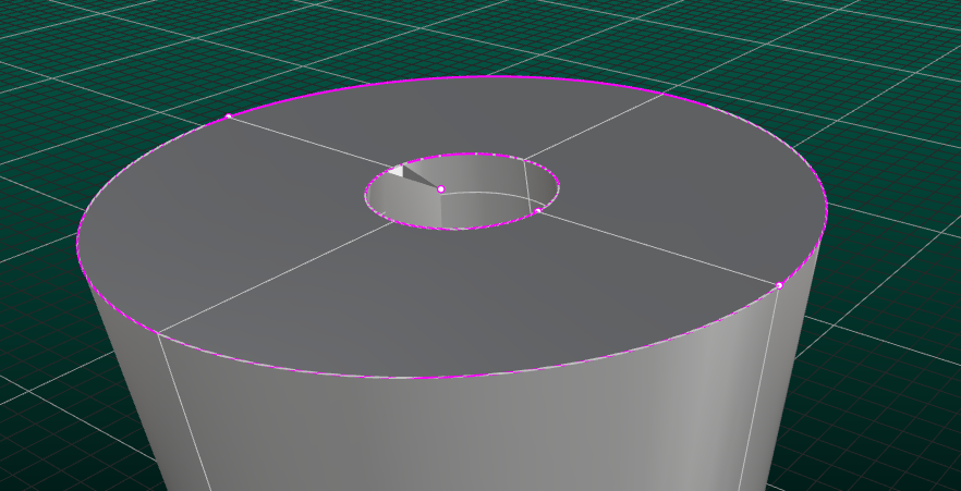
This doesn’t appear to be a tolerance issue. Elementary surfaces, such as these conical surfaces, are represented differently both internally and in STEP files in different applications. Because of this, it is more difficult than you might expect to translate them correctly. In this file, the STEP representation of the interior cone has its natural seam on the left, but the 3D trimming curves are such that the seam should be on the right. We attempt to find inconsistencies like this and take them into account. This particular problem does not get caught for some reason. All we can do is improve our code as new problems are reported. I’ll get on this one ASAP. Thanks for the report.
1 Like
RH-65208 is fixed in Rhino 7 Service Release 10 Release Candidate