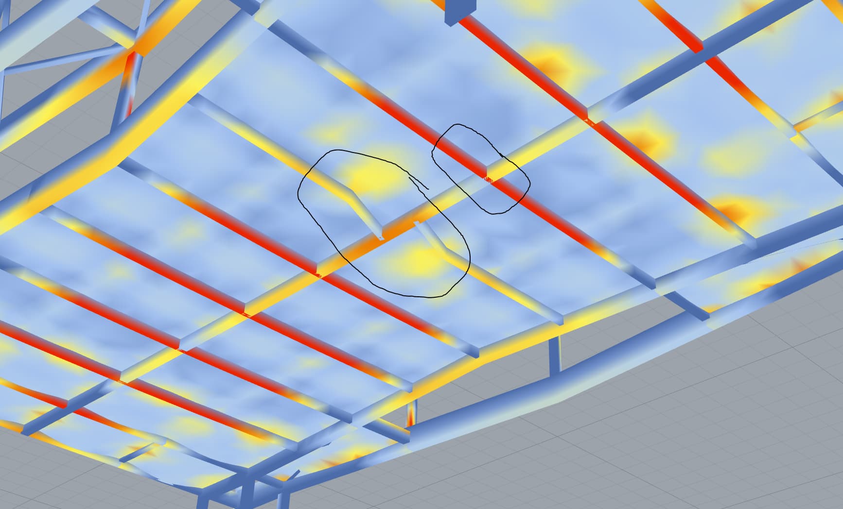
At the moment, the secondary beams that are in pairs act as one. How to make them act as two separate leaning on the primary beam in the middle. It should be clear after looking at the picture.
(this is the preview of BeamView with utilization option where red is above 80%)
Hi Kp, I don´t know if I understood you well (Attaching some example GH script may help). In any case, I´ll do my best.
In order to Karamba3D understands that two or more beams are attached to each other (i.e. joined together), their end points must be the same position. Are your secondary beams made of (at least) two beam elements? In addition, the primary beam in the middle must be divided into the same number of segments as the number of secondary beams… otherwise the beam element end points will not match between primary and secondary beams.
The problem is that I expected the middle beam (i oversized it in this picture) to take most of the load. But it seems that it is the secondary beams that take most of the load as if they spanned across without touching the middle beam. Situation A is a test. This is a zoom-in picture of the test with situation A. After I slide secondary beams apart (ending all line at the same point) I get much less red on secondary and more yellow on the middle primary which is what I expect.
Hi, would you press Ctrl-M to activate mesh visualization? Otherwise I can’t figure it out how the finite elements model is set…
What kind of forces are you using? Mesh load on the floor? Surface mesh points must also match beams elements end points. Could you check this? Model view would help to visualize how loads are injected into your structural model.
Hi! From the first picture in post 3, it is clear that the secondary beams must carry almost all the floor load… note that the long girder in their middle does not have any column to transmit forces to the ground. Am I right?
Regarding to your test B, the end points of the kinked secondary beam match some point of the mesh, but the other parts of it do not. See 2nd image in post 5.
You are right that not having columns on the middle girder matters for Karamba. After adding columns to it (black marking) secondary beams work as expected.
But my intention for this structural system was to have the trusses highlighted in green transfer the load from the middle girder.
It is not the problem of endpoints or vertices of mesh meeting. I divided the beams evenly and there is a lot of contact points on all sides of the meshes.
Vigardo, thanks for your help. If you can find some time to look into script that would might shorten this discussion and be so helpful. Thanks for all! (below is script) 220305-fragment 10-karamba.3dm (593.8 KB)
I don’t understand structures well but it seems that even though the middle girder have no columns it should be able to take the load from secondary beams and transfer them to the truss.
Hi, great job testing. I think your FEA model is ok.
What you say wrt middle girder depends on its stiffness. You can try to use a very high stiffness material just for such middle girder, i.e. E=10000 GPa. This should make it transfer loads to the truss as you expect.
Keep in mind that bending stiffness depends with beam length (d) as 1/d^3. Since secondary beams are much shorter than middle girder the load is not transfered to the truss effectively. It seems that something similar may happen with the truss as well. Truss must be stiff enough, otherwise it will not carry the loads effectively as well. (A truss should be relatively stiff, but it depends on your cross sections selection)
adding extra bracing to the grider solved it. Thanks so much for this
I was trying to replicate the structural logic of Croydon train station in London
Last question:
In the Croydon example, they used rigid frame without bracing so people can pass through the truss freely. Can I achieve stiffness in the middle girder not by adding bracing but by fine-tuning post to beam connection in the girder? Is that a job for Beam Joint component. Or I better model grider as mesh with not a stright shape wider at the bottom and top (It should be glulam so I can do funny stuff with it also because it is a student project)
I think you can try to use plates instead of beam elements to model (or just reinforce) the posts (columns). I think that as long as you stiffen the middle truss, the more load it should support. But you must stiffen lateral trusses as well, not just middle one.
Perhaps you can maintain the bracing just in the middle truss and stiffen joints somehow in lateral trusses.
I put together two sheets that describe an analysis of my diagrammatic design proposal. But then I see some contradiction between different analyses of the same structural system.
Purple beams are less stressed in the area of the column in this picture (below)
But then when I take these trusses and analyse them on their own, the same area is the most strressed (pic below) which contradicts the previous result. I cannot figure out what I do wrong.