Split a Complex Terrain

Hi experts.

I figured it out (actually @Holo did) how to mesh this terrain and i am very satisfied with the result (thanks to the plugin Holo made in the follwing thread [ New: TerrainMesh plugin (in alpha/beta) ]). Now, since the mesh object is so big, i would like to split it in order to work it by “steps” so I dont need to have the full model being processed while working. So I tried to split the mesh in 3 parts (2 vertical cutting surfaces) but it ignores any command I run (MeshBooleanSplit/Difference, MeshSplit, etc.).

Basically, the main goal is to be able to edit the mesh between steps without having the full model in the working space and consequently slowing the process. Dont know if it will help in the end but i think it will (please correct me if i am wrong)…

I am going to leave a WeTransfer link of the .3dm file (https://wetransfer.com/downloads/f3c07e616813e37379649e9b5093e51f20191110194744/e58d9eef44143024c5c3a81e7b0efe9720191110194744/6333d1 ) so if someone can help me (preferencially you @Holo since you are familiar with the file and a Rhino expert) I would be very grateful. @Pascal you are also invited to this “party”. I hope at least one of you can fix this or anyone that reads this (i am begging rn).

PS: I also noticed that other people are having the same issue in V6. Is it only happening to this version or in V5 happens the same?

Cheers,

  • T
1 Like

I can split parts of this mesh with my Python/C++ script TrimMeshForDD but not near where you already tried to split it.

Can you provide a link to the mesh without the the split attempt?

Regards,
Terry.

1 Like

I will in a second. But first let me understand…

In how many parts can you split the mesh and why can’t i/you split it where i/you want…? Does it split all the mesh object or only parts of it?
And if you manage to split it, will it still be editable within separated objects?

New file without attempt to split: https://wetransfer.com/downloads/0125bb58304a9a2036b510e4a16da1cb20191110224217/424f9d3cc7c74fd99e112f91d4e7fd9920191110224217/529e55

Thank you Terry. I appreciate all the work.

I am having to improve my script in order to split your mesh properly. Right now I can get it to split near where you had the cutting plane. It takes the script about 2 sec. But I have cleanup to do because when the cutting curve is projected onto the mesh by calling:

Curve.ProjectToMesh(curves, [meshGeo], V3d(0.0,0.0,-1.), tolerance)

the curve is broken into over 300 pieces . So I need to improve my join_segments procedure to handle this case. I will let you know when I have it working and then I will post the script.

Once it is properly split, you will be able to edit the separate pieces. This could work. I just need to keep my head down and fix it.

Regards,
Terry.

2 Likes

Wow.
I admire your confidence Terry. I am pleased and relieved to know someone is solving this “puzzle.”

Just to keep you posted with the file: the layers VBOX1 and VBOX2 contain the cutting planes which I/we wish your script can cut the TERRAIN. I can’t help you with anything else. If I actually can PLEASE let me know.

My best regards.

After removing 1815 degenerate faces from your mesh and with a few bandaids applied to my script, it took the script 15 sec to split your mesh at the VBOX1, VBOX2 locations:

Now I need to cleanup the script so it will be practical for your to use. Below is a link to the .3dm file with the split mesh on Layer Pieces under the Parent Layer Split. The cutting curves I used were copied from yours and are on Layer Ordinary under the Parent Layer Corners.

More tomorrow.

Regards,
Terry.

3 Likes

:heart: for this community.

What do you mean with “degenerate faces” and how did you remove 1815 of them from the mesh? I hope It was not manually. Did you make a script for this?

If I have any more questions i will let you know. Thank you.I will check the file and keep you posted of the results. I am grateful for this @Terry_Chappell.

My biggest regards.

Hi @Terry_Chappell. I have checked your file and I see that you managed to split part of the mesh but not all of it. Only the middle part is “splited”. The other two are still “together” and I want them seperated since the main goal is to be able to “explode” and edit the mesh. Do you think it would help with less “mesh faces”?

Regards.

Yes I am aware that the top and bottom are still joined. Since they are disjoint it is easy to separate them with one Rhinocommon command. I just need to use a different flow thru my script and this step will be included.

My script includes a half dozen options for cleaning the mesh. I used the option for removing degenerate faces and then moved the mesh from Layer Cleaned back to Layer Normal to continue working on the mesh. Removing the degenerate faces only took a few seconds so not much effort on my behalf. Degenerate faces have zero area due to vertices with the same coordinate or all three vertices being colinear.

When I get to my office I will work on getting the script back into reasonable shape and then put together some documentation on how to use it. It has an Eto Forms GUI which makes it easier to use.

1 Like

I also noticed when I opened the file that the mesh is a bit “messy” between the splits. Is that because of the removal of the “degenerate faces”? Are you going to improve your script on this matter? (Please) I don’t want to be picky about it since when splited they are easily edited but I had to ask :slight_smile: Not sure if i did undestand the Rhinocommon stuff. Are you going to send me a command file when you end your work in your script?

Thank you.

The mesh is cut apart at the splits, is this what you want? It is split just like the Rhino Mesh Tools Split command splits the mesh. The line between the splits is clean, with minimal extra triangles injected to complete the split as shown in the two screen shots below:


The degenerate faces that were removed should have no impact on what you see as they have no area. The areas of the mesh between the split lines are not changed by the splitting operation.

Is the messiness you are referring due to the change in appearance of the Shaded View between the original mesh:


and the split mesh?

This is due to a change in the surface normals. I can unify the surface normals in the split pieces which makes the split mesh look like the original:

I think this is what you want. Below I will show you how to run the script to get this result.

Here is an updated link to .3dm file. Load this into Rhino as the first step to running the script.
Please note that the script has copied the original mesh to the Layer Start Mesh where it is preserved. I made one change to it though; I removed the degenerate faces that were causing problems with the script and were making it a Bad Mesh according to Rhino’s Mesh Tools-> Mesh repair wizard.

The script is written in Python. Put the script
TrimMeshForDD.py (360.2 KB)
in the folder at:
C:\Users\Terry\AppData\Roaming\McNeel\Rhinoceros\6.0\scripts
with Terry replaced by your userid.

To run the script, push the TRIM button in the Standard toolbar:

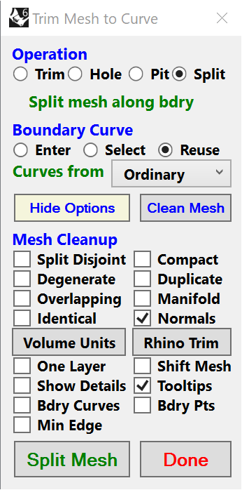
When you push the TRIM Button, the Form for the script should appear:

Before you push the Green Split Mesh button to split your mesh, click on the Show Options button and turn on the mesh cleaning operation called Normals so that the Shaded View of the Split mesh will look like the Original. Here is what the form should look like just before you push Split Mesh.


The cutting curves are on Layer Ordinary and must be closed curves as shown in Green in the above example and below. The curves cannot overlap but a curve can cross the mesh more than once or lie entirely within the mesh. Below is a simpler way to define a cutting curve to split the mesh into 3 pieces with a Closeup on the right. Be sure to Click on the Closeup for a better view of the thin Green cutting curve.

When Reuse is selected on the form, the cutting curves on Layer Ordinary are used. If instead you select the Enter option, then the curves on Layer Ordinary are erased and you can manually enter a new curve after you press Split Mesh. When entering the last point of the closed curve, do not try to click on the start point. Instead just click nearby and press Enter to let it autocomplete. If you want multiple curves on Layer Ordinary, then you can copy an existing curve on this layer (select curve, Ctrl+c, Ctrl+v) and modify it. Or you can make a copy of this layer (right mouse button when over Layer Ordinary) and then use the Enter option to place a new curve on this layer. After each new curve is entered, move it to the copied layer. Once all curves have been collected on the copied layer, move them to the Ordinary Layer when you are ready to split the mesh. The simplest way to move the curves is to delete the Ordinary Layer and rename the copied layer to Ordinary. To delete a layer, click on it to make it active (highlighted with blue stripe) and hit the Delete key then say Yes to remove the layer and the objects it contains.

You can even used curved cutting curves to split the mesh as shown in this example:


This cutting curve was entered by selecting the Enter and Curved radio buttons before pressing Split Mesh and drawing the freehand curve.

If you want to do some standalone cleaning operations on your mesh, first push the blue Clean Mesh button on the Form. Then select the options by clicking on the blue Show Options button:


Select from the 8 options in the top half. I suggest turning on Show Details in the bottom half so you can see the details of the cleaning operations in the Command Window. Push the green Clean Mesh button when you are ready to clean your mesh. The cleaned mesh is put on layer Cleaned. If you want to use this mesh for more operations, you need to copy it to the Normal layer (delete whatever is there first). If you want to perform some of these cleaning operation on your mesh while splitting it, just go into this options panel and select them before you split the mesh.

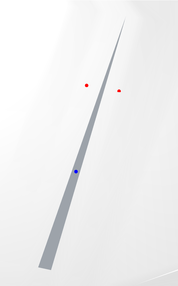
The only other thing wrong with your starting mesh is that it has 36 intersecting faces as show by the red and blue dots in this perspective view:


My script can remove these and then you get a clean mesh report by Rhino:

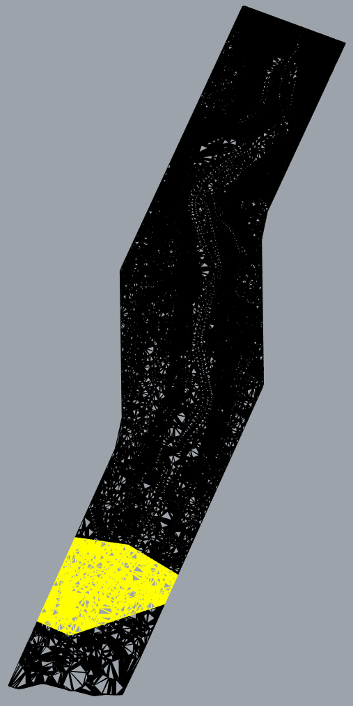
However, the downside is that 1 face in each intersecting pair is removed which likely leaves holes in the mesh, an example of which is shown here:

You could go around to each of the locations and try to manually fix these using the Fill Hole option in the Rhino Mesh Tools toolbar image or you could just leave the intersecting faces in your mesh and ignore them. To remove the red and blue points, go to the Command Window and type selpt and then hit the Delete key.

Be sure to use the Tooltips built into the Form to learn more about each of the fields of the form. To see a Tooltip, hover the mouse pointer over a field. If you find the Tooltips too distracting, then go to the options panel and deselect Tooltips.

The script still needs more work to make it more robust and handle a wider range of meshes. I will update the attachment above when it has been significantly improved.

Regards,
Terry.

1 Like

Hi Terry.

First of all, I would like to thank you for the incredible effort and time you are putting in this.

Secondly, I have some questions about your instructions but I understood most of it. So here it goes:

  1. I dont find exactly the location of the folder that you suggested me to save it. I found a “Plugin” folder and inside contains a “IronPython” folder in which contains a Library (“Lib”) full of scripts like the one you sent me.
    If this is the right location, I just need to drag it here and the TRIM tool is ready to run in RH? I am guessing this is the correct location to save the file but I would like your confirmation.

I understood most of the instructions to the commands and I am looking forward to run this and try it out.

1.1
Does the layer “Ordinary” from your script only contain cutting elements that you select or enter? As soon as you select or enter the cutting curves and after you “Split Mesh” these “curves” redirect to the layer “Ordinary”? Am I correct?

1.2.
In order to split the mesh do I need to position the “new” cutting curves in the same “Z” coordinantes you used in the file or can I position them where I want? I figured it is the second option (in bold), but I just want to make sure I don’t miss nothing.

Should I also do “Mesh Cleanup” or have you already done it in the last file you sent me? And why? :nerd_face:

Is this script safe from crash errors that might oblige me to SAVE every time before I run it or is it stable?

_______________________________________________________________________ NOTES:

Yes, I was exactly mentioning that.
I solved it with the “Unweld” command. As soon as I play around with the command between meshes they go back to normal so I suspect it is a “display” bug of the mesh (?) in RH.

I am not sure if all of the questions make sense. I hope they do.

My best regards,

  • T
  1. It is interesting to see that your paths for Rhino are so much different than mine. I had no idea this could be the case. To find the path I was referring to try doing this:
    In the Command Line type: EditPythonScript and push Enter.
    Then in the Python Editor select: File->Open
    You should see something like below.
    Notice the Path at the top of the window.
    Put the script in this folder and then the TRIM button should work.

However the other path you suggest could also work according to the Module Search Paths for the Python Editor. To see these Paths, in the Python Editor select: Tools->Options and a window like this should appear:


As you can see, the top Path for my Rhino installation is very close to the Path you mentioned:
AF > SSD(C:) > Programas > Rhino 6 > Plug-ins > IronPython > Lib.
But it is the 3rd Path of this window, C:\Users\Terry\AppData\Roaming\McNeel\Rhinoceros\6.0\scripts that is a more appropriate location to store scripts for my Rhino installation. Take a look at your Module Search Paths and put the script in the one which looks most appropriate. As long as the script is in one of these Paths the TRIM button should find the script and run it.
1.1 Yes, Selected and Entered cutting curves are placed on Layer Ordinary. Any preexisting curves on Layer Ordinary are deleted before the Selected or Entered cutting curves are stored on that Layer.
1.2 Any new cutting curves need to be above the highest Z of your mesh so they can be projected down on the mesh. If you use the Enter option, the Z of the cutting curve is automatically set so it meets this requirement. But any Z above the max Z of the mesh will work.
2. The meshes on the Start Layer and Normal layer have had the Degenerate Faces removed but nothing else. These meshes still have overlapping faces as I detailed and gave you suggestions for how to deal with them. The primary reason to do Mesh Cleanup is so the mesh will work with your tool flows. Typically you want to get a Good Mesh report from the Mesh repair wizard tool which is the second Icon from the left in this snapshot of the Rhino screen:
3. The script on my system is quite stable and does not crash Rhino. I have had it crash Rhino when I am developing new code. But once I finish testing the new sections of code, it typically does not crash. So I do not think the mesh will crash Rhino if you are just using it to split the mesh as I have shown you.
4. I have never use the Unweld command. I think it must change your mesh. Do you want the split mesh to look like the original? It now does by using the Normals cleanup option. So why are you using Unweld? Does it improve your mesh in some way? Can you show a picture of this?.

Let me know if you have any questions or would like enhancements to the script.

Regards,
Terry.

Hi @Terry_Chappell.

I hope everything is going well for you during this horrbile phase the world s going through.

I come here asking if you can help me split (same exercise done before) the same edited file. The script you you gave me is not working anymore and I dont know how to put it to work.

I can send you the file via wetransfer (100MB) with the two reference lines to split.

I am in a bit of a hurry since I want to print this bad boy to 3D in order to finish the all thing. Please, help me.

Thank you for everything.

Cheers,

T

Send me a link to the file and I will take a look.

Regards,
Terry

I will send you in 12 hours exactly.

Cheers,

T

Ok I will look for it. I have not run the script or done any Rhino work for over 6 months so I will try to get back up to speed while I wait for your data.

Regards,
Terry

1 Like

Looks like I am running out of time. I move next week and have to send the parts of my computer ahead on Friday. So I will only have a little time tomorrow before I have to disassemble my computer. Sorry I am running out of time here. Once I am moved, unpacked and have reassembled my computer, I will have a lot more time to help out on the Rhino Forum.

Regards,
Terry.

1 Like

Hi @Terry_Chappell.

I send you the link with the file.

( wetransfer link: https://we.tl/t-Ru17EXeItc )

The two reference lines to split the mesh are in the following layers:
“01. INTERVENTION AREA” and “02. BRIDGE AREA”.

Also, I would be very pleased if you could send the same Slope and Elevation map you did previously to the “unedited model”. It would be a very nice and awesome extra to my teachers and myself.

With nothing more to add, I thank you very much and I wish you lots of health and fortune. For a second, I thought I would never talk with you again. Very glad to hear from you.

We will keep in touch.

PS: Today is Thursday. Are you going to have enough time to do this? If “YES” I thank you VERY much. If “NO” when will you have time to reassemble your computer and make this happen?

Cheers,

T

T,

I tried working on your mesh but I did not have much success. I could not join it into one mesh using my script (this is required before splitting the mesh). Thus I could go no further using the script alone. So I used the Mesh Repair Wizard in Rhino’s Mesh Tools to examine the mesh and found that it had many problems (non-manifold and intersecting faces mostly). I had the Wizard try to repair these but it could not fix enough of the problems to change it from a bad mesh to a good mesh.

Next I selected the 6 main pieces and typed join on the command line in order to join them into one mesh. Then I hid this large piece and deleted the remaining 20 or so smaller mesh pieces. After this I used my Drone Maps script to make an elevation map of the one large piece. It looks like this:


There are holes where the smaller meshes were removed. I tried making a slope map but it did not make much sense because the slopes are so steep in so many places:

I am out of time now but should be back on line next week if things work out.

Here is a link to the .3dm file of my last result.

Hope I can be of more assistance in the future.

Regards,
Terry.