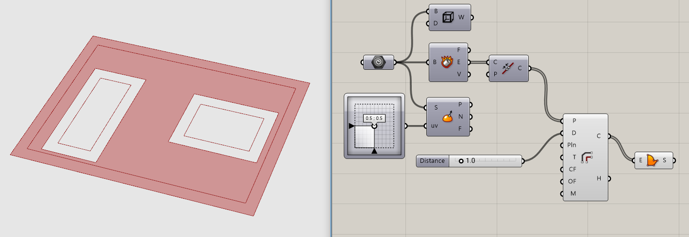
May I ask how to get the inward offset of the boundaries of a surface with holes, sth like:

I tried the polyoffset tool, but it doesn’t seem to work:

Thanks.
I would debrep, then connect list item to edges and select all the edges for the hole, join curve then offset.
Thanks, @victorlin.
However, I’m unable to get the offset correctly.
The offset seems to happening in both directions, inward and outward.
offset surface with holes.gh (11.6 KB)
Thank you very much, @m_tsiliakos and @victorlin.
Yes, @m_tsiliakos, your solution is the most effective from which I learned a lot.
Dear @m_tsiliakos,
I still got problem with the workflow based your suggestion.
It seems for surfaces on the same height, it will produce the offset outwards:
… whereas for surfaces on different height, the offset seems to be correct inward one:
Can you kindly take a look of the GH file attached and advise which part of the workflow is causing the inconsistency?
Thanks.
BTW, the following group of components is to identify if there are surfaces with holes which will bee processed differently:
offset issue _v001.gh (24.0 KB)
Why is this thread title labeled “[solved]”? And why is this so complicated?
Thank you very much, @Joseph_Oster, for your clean solution.
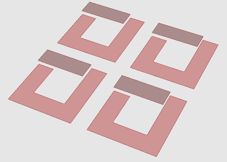
For the surface group 4 as shown below, I merge all connected breps before using your workflow to do the offset.
However, four of the breps due to different orientations were offset in different directions as highlighted below.
I tried to make the normals of the merged breps the same before the offset, but the output surfaces still have different normals, and this merge Brep -> check normal -> offset approach doesn’t work for the previous three cases.
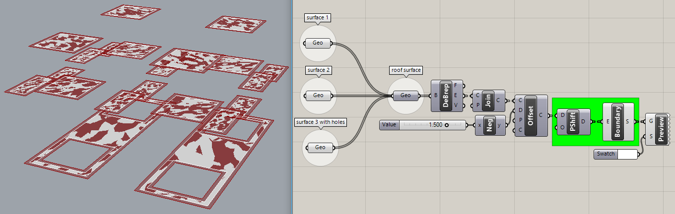
May I ask ask the function of the shift paths component here?
Appreciate your advise on a general solution that can deal with the four different scenarios consistently.
Thank you.
offset issue_2017Nov23b.gh (28.1 KB)
So if this isn’t “[solved]” to your satisfaction, can you please remove that word from the thread title?
It does nothing at all here because none of the surfaces in the “surface 4” ‘Geo’ param have holes in them. If you look back at the version I posted ( offset issue_2017Nov23a.gh ) and examine the data tree output carefully at each component, it will become clear, Without that ‘PShift’, ‘Boundary’ would fail to recreate the holed surfaces. Try it without ‘PShift’ and see what happens?
Most of the trouble people get into with GH happens because this detailed examination of data trees at each step is not done. This is also true of the code in your post today. It gets pretty tedious to repeat this same advice over and over. The general solution is to avoid trouble in the first place instead of creating it and calling for help. Keep the car on the road and don’t drive into a ditch! ![]()
I’ll get back to you again after I make some coffee.
The solution posted above by @HS_Kim is complex but appears to work well; I suggest you use that.
Regarding offset issue_2017Nov23b.gh that you posted today, here are a few comments, for whatever they’re worth:
Did you notice that it fails immediately (at ‘Boundary’) using “surface 3 with holes”?
In the white group, you are comparing the surface normal angle to ‘Z’ - do you realize that only works with planar surfaces in the ‘World XY’ plane? Not very general purpose.
You can see that the original 16 surfaces all have the same color (a clue!) and surface normal direction. After ‘Join | Boundary’, four of the resulting surfaces are discolored and have their surface normals flipped:
You try to fix that with ‘Dispatch | Flip | Merge’, and the surface normals all match after that, but those four surfaces are still discolored, which is an indication that they are still reversed somehow (probably due to edge curve direction?). These are important clues, not to be ignored.
Those four darker surfaces offset out while the U-shaped surfaces offset in, which gets fixed by ‘DeBrep E | Join’ before ‘Offset’. I guess you know most of this already, I have to walk through it just to understand it myself.
So, knowing all that, I copy your “surface 4” ‘Geo’ param into my offset issue_2017Nov23a code and it works perfectly for the sixteen surfaces. The expectation that it should always ‘Join’ adjacent surfaces is a flawed assumption. The question becomes, how to recreate those joined surfaces without breaking code that is known to work otherwise? See what I did there? Re-frame the problem!
Here’s something that works, the ‘join/flip’ white group, though honestly, I’m not quite sure why. The peculiar thing is that it doesn’t matter if you flatten the input to ‘Item’ for selecting a ‘Flip G’ guide curve or indeed, whether or not you use a guide curve at all?!
P.S. Examining the ‘Flip Curve F’ output is interesting in the three scenarios I mentioned. ‘Flip’ works as I expected but this doesn’t explain to me why it always fixes our main problem?
Dear @Joseph_Oster and @HS_Kim, thank you very much for your detailed advice!
Allow me to digest your suggestions and try out each solutions.
Your very generous help is greatly appreciated !