Hi, I don’t know if I need to start a new post, but I would like to know what is the best way to write the definition for what would most resemble the Slab command in Rhino or in VisualArq. I know that VisualArq has a component or a few for slabbing. but they haven’t released a stable version for V6, which is what I am using for various other advantages. I also would like to go through the mechanics of setting up the definition to learn better. I’m gonna take a stab at the definition, but unfortunately I cannot easily sketch my idea to scan and upload yet, so any tips would help. This is kinda the closest post I could find, but it seems outdated: http://make2d.blogspot.com/2011/09/making-slabs-with-grasshopper.html
Cluster this:
slab.gh (6.5 KB)
Substitute ‘Clipper’ plugin for native Offset curve if it fails.

slab_cluster.gh (9.2 KB)
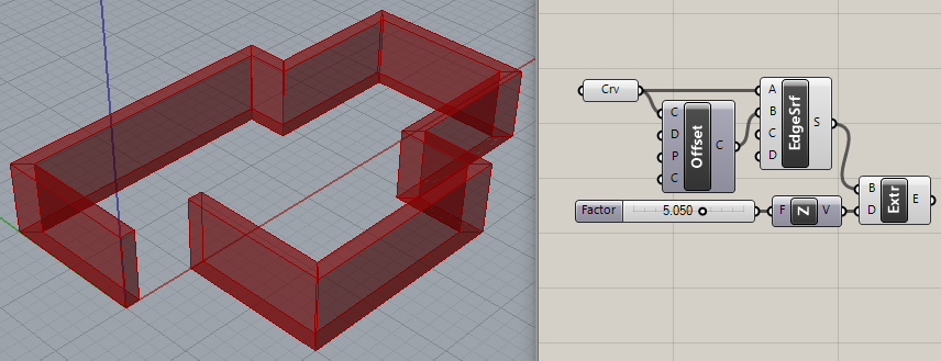
Hi Joseph, that’s a cool solution, thanks! However, I found a different way to do it, and now have different problem that has an easy cheat, or the preferably harder method to get what I want. This time I’ll attach what I’ve been working on. So, if you look at the screenshots, you’ll see I’m at the beginning of designing some cabinetry which has a baked version of some rounded corners and has one side of surfaces further extruded than the other. In making the definition I am stuck where I rotate my front set of edges to produce the desired angle. The edges rotate and geometry is generated, but the edges furthest from the center (on SIDE B) of rotation are no longer planar with the edges that were not rotated (which you can see in the Bake). If you see my GH def and the screenshot, it’s kinda lop-sided in top view. Is there a way I can rotate those edges and make the points follow the existing extruded surface that I created for reference?
Mimi-Cucina.gh (39.6 KB)


Sorry, that looks more like work than fun. Did you set ‘Display | Preview Mesh Settings | High Quality’?
Totally understand, maybe I should make a new post, cuz I need to get this right for fabrication.

I can’t see much of anything in this file. It appears to break down at the first RDiff. See the orange wire coming out?


The ‘OUTER PROFILE’ measures 2000 X 3000 (???) and the Offset Curve is only “6”? That’s tiny considering the large dimensions. I can bypass RDiff and the model seems to work again…

As I suggested previously, ‘Display | Preview Mesh Settings | High Quality’ fixes the cut off corners, though I can still see the “gap” you referred to. Yeah, this is work!
OK, that so-called “gap” is caused by the simple fact that you are rotating the bottom of the box up instead of slicing the box off. Seriously? This is the problem? Wow…??

I’m not sure what else you’re trying to do in this model? This gap thing is OBVIOUS! Not sure what else to say?
Oh, thanks for the display tip, definitely helps. As for the orange wires, I don’t get anything like that. Don’t know why you get an error for bifocals, but yeah, the 2000x3000 is mm, it’s for a kitchen product, and I am using a sheet material that is 6mm thick. Still hoping to get rid of that gap, but right now I’m using another solid difference to create the angle. It would be sweet to achieve my original goal though.
So, I already told you that I sliced off the box as a short-cut, the problem is that I will need to be moving edges throughout this model, that’s why I’m trying to figure out this problem.
Look @cartermarino, you won’t get rid of that gap if you don’t understand how you created it. Do you?
Oh, I absolutely know how I created it, the problem is I still can’t figure out how to Scale 1D the curve along the rotation angle towards the plane where the gap will end.
I’m gonna experiment with shear to see if that solves my problem.
I’m sorry to be so blunt but I don’t think you have a clue.
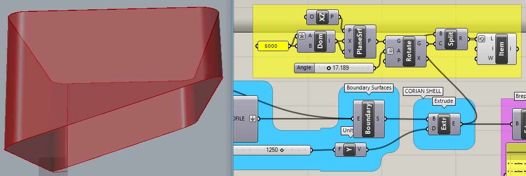
The yellow group avoids the gap by slicing the extrusion with a rotated plane. The green curves are the ones you rotated that created the gap in the first place.

Mimi-Cucina_2018Feb19a.gh (29.9 KB)
Scaling is not the answer. There are many ways to do this. Hope this helps. Good luck.
Thanks that was really helpful, but for whatever reason, I still get a runtime error that the split didn’t work. Why would it give me an error if I am running your exact code?

Because you’re using GH version 1.0.0004 and I’m using version 0.9.0076? GH has become a train wreck that way. It has turned into a tower of Babel.
Does this work any better?
Mimi-Cucina_2018Feb19b.gh (27.0 KB)
What about this version? I discovered that your initial ‘OUTER PROFILE’ rectangle used a weird ‘P’ (Plane) input value (labeled “Plane XY???”), which I replaced with a World XZ plane who’s origin is at Y = -1. This is to make sure there is a “clean” intersection with the rotated PlaneSrf.

Mimi-Cucina_2018Feb19c.gh (22.1 KB)
P.S. I also used the same plane as input to Offset. Precision matters!
Yeah, absolutely works, since I’m new to grasshopper, I would have never thought of this solution, but it works great. Thank you!
So I was just trying to get the plane oriented XZ but didn’t know how, your set of components make a lot of sense. It’s too bad GH v 1.0.0004 is malfunctioning.
Note that I also used the same plane as input to Offset. These details need to be correct, no matter which version of GH is being used. It’s possible that fixing the plane inputs allows the plane intersection in version ‘a’ to work in both?
P.S. To compensate for the ‘Y = -1’ origin of the XZ plane, you need to change the extrusion ‘Y’ value from 1250 to 1251.