Is there any way to control the location of the seam during the execution of the pipe command? I am working with degree 2 curves mostly and some pipes have the seam to the inside and some go to the outside. The behavior is unpredictable and I need consistency for use of those pipes down the road.
You can flip the direction of the curve to make the seam go on the other side. Or you can change the seam after the pipe is made by using the SrfSeam command.
Doesn’t this create an extra control point that otherwise wouldn’t be there?
For me, if a pipe is created on the Floor plane, often it is difficult to intersect with a surface on that plane made there.
Circle around curve is the only other option, then you can direct the seam of the circle to be away from where you are splitting something. Of course, that’s not a good solution when you want to pipe several curves. It’s like the default option isn’t quite optimal. Does that make sense?
Here are some other things that came to mind as well:
OrientonCrv - multiple curves on multiple target curves (in the case of copying a section to many different rail curves, oriented correctly)
Pipe inside or outside of a curve - probably would need a roadlike/freeform option?
Make a surface periodic, in one direction (think of an open ended pipe form, which has a discontinuity at the seam)
I should probably break this off into a new topic though… basically ‘groove-like’ forms in general I find a bit troublesome. Especially when they start crossing over each other. Trimming with pipes again makes more mess quickly. Although I think my conclusion is that the pipe just isn’t really the right way to do it. I’ll make some examples later.
One more thing about the “Pipe” command. While using degree 1 lines (the most basic straight line with two control points total), is there a way to tell Rhino whether to build a pipe (cylinder) with degree 1 or degree 3 (with two extra rows of control points inside the surface) along the line?
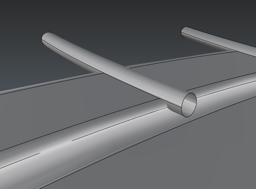
See above. The plane in the background which eventually splits the pipe does so very close to the seam of the pipe (coloured yellow) and so can be problematic for downstream . I would prefer not changing the surface seam 10/15 times, especially when using round pipes (so then running extract each time too).
If the curve to be piped is in green, the start of the complete arc should be as far away from the Brep as possible, in the frame - either of the two red points. Even better, an up/down logic too could be applied so as not get end up with two surfaces after the splitting has been done.
I think I could probably do a Python routine for it. But I would need some advice along the way perhaps, or pointers/stuff to consider
I would be VERY interested in any scripting to support this piping issue. I deal with it all the time and can’t count the hours lost to SrfSeam. My own scripting capabilities are not up to the challenge.
There is also another issue with “Pipe”, or actually the way cylinders are being split with the “Isocurve” option of the “Split” command. When you do so, by default Rhino will try to split the pipe (or the cylinder) along its length. This behaviour is counter-intuitive, because in most cases the modeler wants to split the pipe so that it gets shorter. So, the modeler is forced to click on the “Toggle” option in the command line or access the keyboard to press the T key and press Enter. The latter is not convenient for those who use 3d connexion devices. It would be more natural if the default split direction is already swapped. It’s also strange that the Tab key does not double as a toggle for the direction.
So I guess swapping the defualt directionof how the pipe is corrected? Yes splitting along the length is counter intuitive indeed. Although I hadn’t noticed, even as a fellow 3d connexion user.
Yeah, not sure why the “McNeel” team opted for the counter-intuitive direction for the “Split” (via Isocurve) and “Extract isocurve” commands on pipes and extruded surfaces from circles. It’s inconsistent when you compare it with the proper direction for both of those commands applied on cylinders built with the “Cylinder” command.
In short:
Cylinder and Extruded surfaces (only with the “Extrude” command) have the proper direction for both, “Split” via isocurve and “Extract isocurve” commands.
Extruded surfaces (only with the Gumball) and Pipes have the wrong direction for the same commands.
Rhino sets the U direction for these objects in a different, inconsistent way…
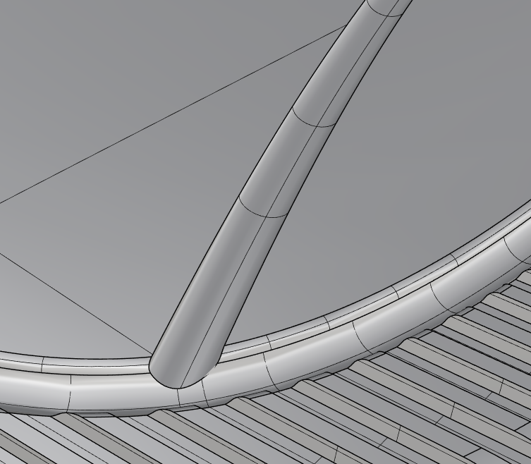
I found a peculiar example which explained things well this morning. Two of these projected curves orient away, so when they are eventually split I will get one surface. The third inexplicably is downwards. I tried flipping the curve, no dice. So I’m not sure what the logic is behind the scenes. But a little more could be nice.
I haven’t had the chance to look deeply into how I would script it. But it would be along the lines of an option which focuses the seam towards a world (or other) CPlane. For me the big ones would be top or bottom. And then maybe an option for the frame to change along the curve so it always points towards that CPlane, although at the point I guess you’re more getting into the region of copying Sweep1.
Also a weird fail by pipe - although I appreciate the curve input is a long way from ideal.
There are two short segments in there near the ends that seem to make the difference - not quite sure how, yet.
At any rate it is fixed in V7/WIP. The miters are not made at 1 but the pipe is complete, if disjoint.
What would you make of the earlier example of the seams of three similar enough looking curves, having one that points entirely in a different direction?
SrfSeam is of course a fix, but not ideal if you also want to align round caps and if you have many (10+) to do.
I just did some tests and the UV direction is still inconsistent in Rhino 7. This is inconvenient in situations where the goal is to extract isocurve or split the extrusion/pipe with isocurve. Example:
Wow, thanks! This is a good start but it doesn’t work on closed curves.
I would definitely consider this useful. I do a lot of work with complicated grooves on complex surfaces. A lot of the design work is done flat then the curves are flowed to the complex surface. I tested with degree 1 lines and arcs - polylines - control point curves drawn on the flat with different directions. When flowed and piped with your script, the seams all were to the outside of my shape. This is exactly my desired behavior.
In the case of the polylines… the circles were drawn correctly at the beginning and end of the polylines but the sweep only occurred in the first segment on the complex surface - and then with issues. Interesting stuff.
Oh yeah for sure, I’ve only played about half an hour an hour literally. I’d be more interested to know what some of a McNeel disposition thinks, as they will know better for error trapping and so on. It’s a real hack so far.
Left the circles in for just as working out. next I still need to make it okay for breps too.