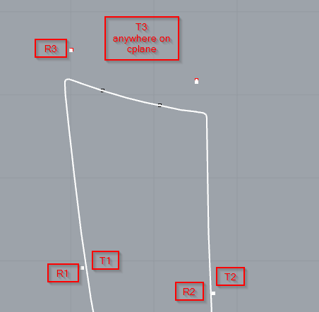
This is probably a simple question. If I needed to “rotate” this to the c-plane so I can plot on my CNC a pattern, what is the best way to do this? I know how to use rotate, but I’m thinking something like this in the screenshot.
This is a boat sunpad cushion and the raised “dots” are snap positions where the head rest is hinged on the cushion. I need to 2D this so when I pattern it, the snap positions are accurate.
I figure if I make a rect outline, I can rotation in relationship to that edge. Hope this makes sense (=
I use that when I need to normalize the whole capture to the plane. If I use that for this small section, I still need to tell it where to go, right? I need 3 reference point, then 3 destination points which could be anywhere. BUT… hmm… if I reuse the two points from the drawn line and the 3rd on the plane, that may work. Is that what you were thinking?
I’ll have to play with this more in the morning. This might work but I think order of reference and order of targets matter. It also appears I can only do one “point” at a time.
If I change the order around the new point can either be WAY off or if I do it in another order it offsets like an inch or so which is expected for a rotation arc.
Red is the new position which may or may not be right? /sigh (=
Grouping points to your objects often helps with future rotations. You can add extra points to create a hinge-like axis for rotation. The 3D rotate works well for this.
Orient3D is one of those commands I never get right the first try.
If accuracy is paramount, protect the original by making a copy of the object, and laying the copy down, and or make a back-up layer. Blocks also work for this, too.
By using points, and the [TAB] key for lines, temporary lines, and snaps, I have only once needed construction plains, and that was for laying out an control panel, on a angle.
If you want the “hinge” line to lie along the edge of the in-plane piece then you will have to twist the two points, i.e. rotate one more than the other.
I would use Orient3Pt with Scale=No with three reference points on the object and three target points on the CPlane.
The first target point determines where the oriented object will be located on the CPlane.
The second target point determines how the object will be oriented on the CPlane. It’s distance from the first point does not matter, only the direction from the first to second points.
The third target point needs to be on the CPlane. It cannot be colinear with the first and second points. Which side of a line from the first to second point the third point is on determines whether the result appears to be “right side up” or “upside down”. Otherwhise the location of the third point does not matter.
Added
Result using Orient3Pt: CushionsDC1.3dm (90.3 KB)
Use of Orient3Pt (Blue scribble shows location third reference point.)
Agreed, if we are simply orienting the two points onto the c-plane. But if we want to include an edge to match the existing one, ie to start building the parts for a 3-d cushion, then the twist is going to make life more complicated. (and renders my original suggestion worthless too, of course)
(I’d probably go old-school: lay fabric on the deck and mark the points, the put it on a flat table, measure the distances and transfer to the drawing.)
Quite, but using another boat analogy, if you apply any orient3pt transformation to a spinnaker you don’t get a flat sail. Here the two points and the edge do not lie in the same plane. If the relationship between the edge and the two points is important (and I am only speculating that it could be) then orient3pt is not going to provide a solution. We are into the dark art of surface flattening (although as we are working with flexible materials and the bend isn’t large, we may get away with it).
If we look at projecting a single snap (dot) based off either newly added temp dots or using the dots from the other snap position, I should be able to orient one dot at a time accurately, right? I believe this was already mentioned in the chat in a similar manner.
(although as we are working with flexible materials and the bend isn’t large, we may get away with it).
Completely agree… we’re not building a rocket. Its off season so I have time to learn some better practices so if I were busy, I’d just have a 2x2 snap patch and snap it on the boat. Which I’m still going to do more or less.
I think what I did in my recent screenshot post works and is basically like what you describe here. I’m still on v5 so I can open your 3dm but I get the gist I think. I dont have a scale option in v5 either it looks… just Copy=yes/no
Attached is a copy of the file in V5 format. Scale option was added in V6. In V5 the command is equivalent to V6 with Scale=No. CushionsDC1.3dm (76.8 KB)