Does anyone have any idea on how I could possibly create this effect in Grasshopper? I am aware that it is possible to create custom G-code and possibly achieve it that way. However these are 3D printed and sliced with a standard slicer, and i believe printed in vase mode as well. I am really struggling to figure this out.
If anyone could help me out I would greatly appreciate your help, thanks in advance!
It’s not quite the same but essentially it is starting with a quad mesh and making each quad face “stellate” or point outwards (or inwards if you prefer) You can get some nice effects.
That looks like the method for creating g-code paths to give the effect in the picture, rather than actually modelling the shape as it looks like lots of separate shapes stacked on top of each other instead of one continuous surface or mesh.
Okay thanks, I will try it later.
I know that in this specific instance he models the shape and export it to obj and use that in standard slicer software, which I’m trying to do as well, but will probably look into gcode generation at some point
Yes, my example does exactly that… creates a closed solid mesh that you can export as .OBJ or .STL and import into a slicer.
You can change the thickness of the mesh so it works for vase mode slicer settings.
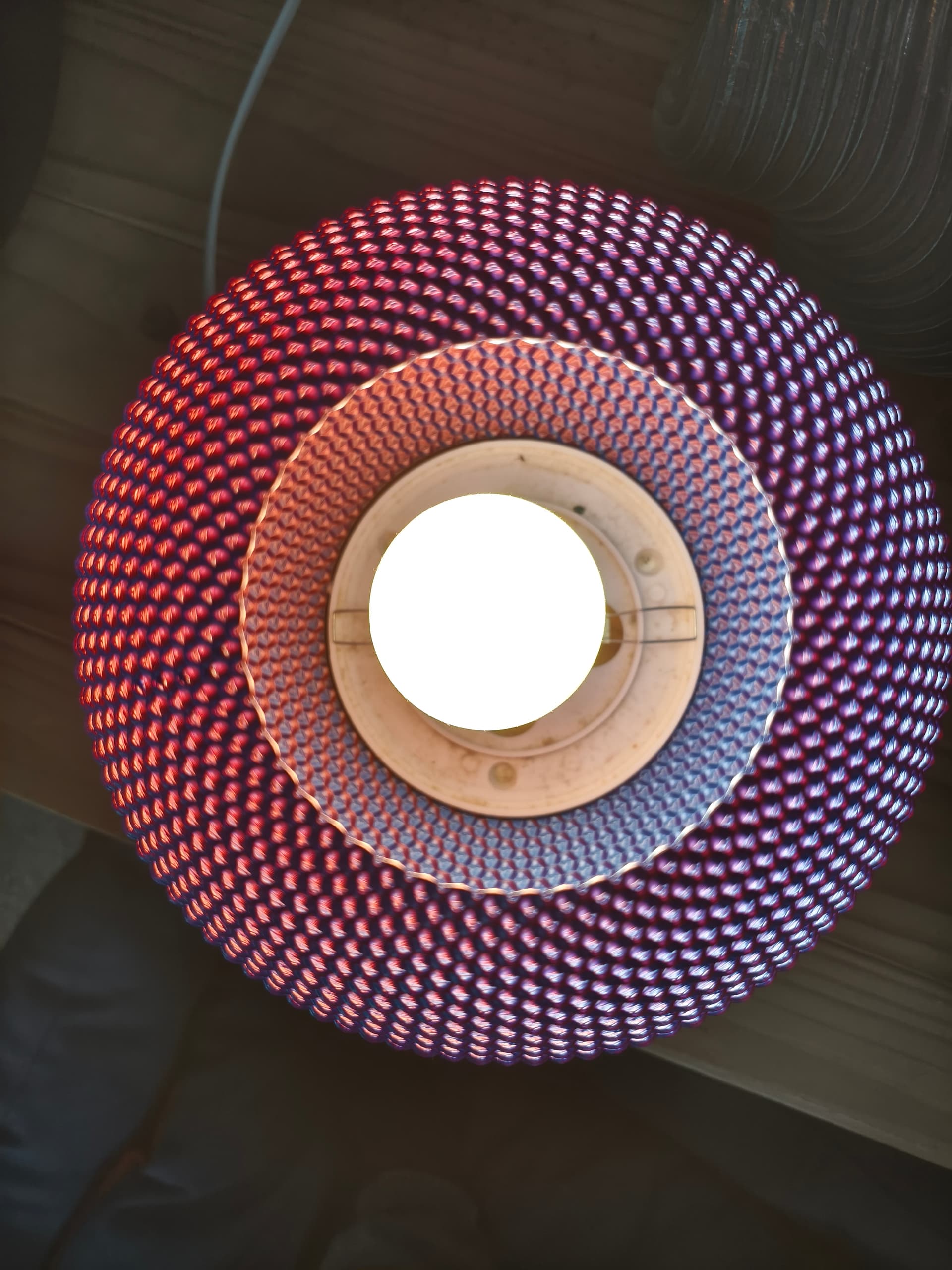
I’m tempted to print one to see what would happen… with the bobbles set to protrude too much the overhangs are too much but it might create an interesting effect… or spaghetti
It’s interesting. Not sure it’s going to make the IKEA catalogue though
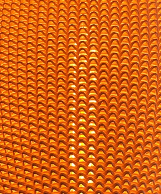
It becomes transparent where the overhang means the filament overlap is too sparse and leaves gaps. A quite fragile lampshade.
Filament is a bi-colour PLA Silk printed in a Bambu P1P in 4.5 hours in smooth vase mode.
I’ve also just noticed that I havent shared my own GH file, essentially what I am trying to achieve is getting the extruder to run along the curvy lines in a way that it produces 1 or 2 extrusion along the path depending on the parameters that I set. I’ve tried a bunch of different methods for slicing the thing, like making it into a mesh pipe. However I also seem to run into issues trying to export and then import as STL, as the object is too big for the build plate - or bigger than I intend on GH.
I am a few days into learning GH & Rhino, but as far as I understand it, the “hole” in the middle should be 100mm, where as the maximum radius of a given circle should be 245mm.
You obviously do not have to look into it, but might be interesting to see what I was actually trying to achieve haha.
Thanks for your help, I’m definitely going to try the bubbles at some point CurvyGaps3D.gh (13.0 KB)
I don’t understand why you are trying to model the actual filament. In order to render it accurately?
I think the way vase mode works is that you can only have walls that are one extrusion thick and that thickness depends on your nozzle diameter. Vase mode is one continuous spiral path from bottom to top.
You can of course just have thin wall surfaces that have an inside and outside that are one extrusion thick with no infill but that’s slightly different to vase mode.
I think it will be easier to slice if it’s modelled as a solid rather than a pipe representing the actual filament.
It looks like they are just creating lofts or extrudes from the curves.
It all goes too quickly to see if the surfaces get thickened but I think they would need to be to work in the slicer.
To turn all the curves in your definition into solids you could offset them by the wall thickness you want, create a boundary surface from each pair of curve and offset curve, then extrude in Z by the layer height.
If you skip the boundary surface then you can use Cap instead after the extrude.
I would say that is definitely done by generating g-code. It looks like an unusually large diameter print nozzle, over 1mm too.
If you search this forum you will find examples of doing this. This is how the clay 3d printers are programmed. You are close to a solution in your file, you just need to join your curves into one continuous spiral and turn them in to g-code for the particular printer that you will be using.
Check that your printer can take a large diameter nozzle first otherwise it will all be for nothing!
I’m pretty sure that it is printed with 0.8mm nozzle and custom G-code, might have to look into that. I have worked a bit on the design and this is how it is printed, very far from perfect but it is a start.
I think I might have to look into custom G-code, but as the 90 day free trial is creeping up on me, I have to think about whether to buy Rhino or stick to my beloved Fusion360 and forget about this project haha Thanks for all the help
I think custom g-code is just text formatting!
i.e. if you turn your curves into polylines then get the start and end of each polyline segment you just format them into…
G1 X123.45 Y234.56 Z345.67 F1234
You also need to work out the extruder commands though.
Then insert this into some standard g-code that has the relevant header and footer for your machine.
Obviously, you run the risk of crashing your machine while you get this dialed in