hi there,
I looking for a long time for a tutorial that will explain how can I generate this kind of mesh-pattern for 3d printing lamp. did anyone know tutorial for this?
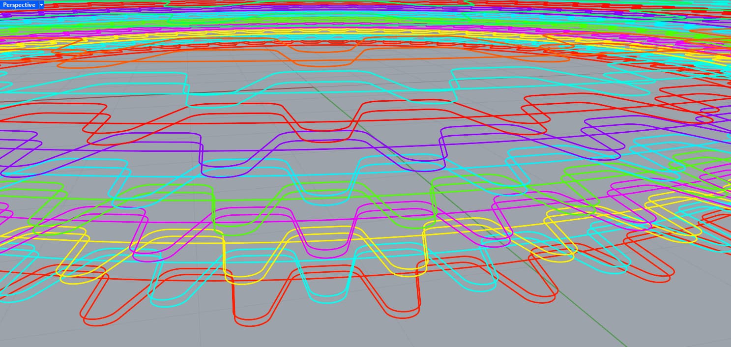
attaching the result I would like to generate:
hi there,
I looking for a long time for a tutorial that will explain how can I generate this kind of mesh-pattern for 3d printing lamp. did anyone know tutorial for this?
attaching the result I would like to generate:
It’s hard to see surface detail in your image so I used cylinders instead. Loft option is “Straight” which produces a polysurface (“Open Brep”) instead of a single surface.
3. Attach minimal versions of all the relevant files
Hello
given the poor description you gave (no references, just a dark picture) I guess you just have to make an undulation of the contour, undulation done using a Sinus or a Cosinus.
bending could also be done but I think it is done by natural gravity and is not taken into account in the curves. Dendro seems the best to mesh these curves. Mesh Piping, Pipe, Curve piping are quite long.
sinus vase.gh (21.5 KB)
it looks like it’s the very same lamp as shown here:
in particular this picture where the lamp is off shows a LOT of important details: https://d2j6dbq0eux0bg.cloudfront.net/images/74715017/4503645619.jpg
if you want to print it with FDM then you’ll need trajectory curves that will be used to create the Gcode for your 3D printing machine
speaking about the structure of the lamp, it looks like there’s a perfect circular layer which gives structure (1) followed by two layers with ondulating protusions on same position (2) (3)
then there’s another package of those (1, 2, 3) where the position of the protusion is swapped, and so on, and so on…
about the bellies, it looks like they are protuding more toward the bottom of the lamp, and less toward the top:
something like this could be a starting point:
each package is like circle, belly_A, belly_A followed by next package circle, belly_B, belly_B
the graph mapper controls how much the bellies are protuding depending on their height relative to the whole print:
this is just a sketch, consider that there’s SO MUCH optimization you can still put on that, like for instance the whole thing is made of straight lines joined into polylines and then filleted -not a good solution AT ALL, but gives you the idea- and also the bellies are now generated as a single point wich makes a pretty steep corner… you might want to insert 2 points instead of one in order to create a bit more curvy wave (and eventually use Interpolate Points with Periodic=True instead of Polyline)
wow!
thank you very much, your explanation is amazing.
im just wondering - I should loft the curve before I slice it or pipe them?
(im new to FDM and PrusaSlicer…)
As @inno said
This design is not really intended to be sliced.
I rendered it in 3d for rendering purpose only.
Can you explain me what this means?
what is the meaning of trajectory in 3d printing and how should I deal with that?
Mainly there is 2 big ways.
and should I do that? just exports the curve and open it with the slicer?
I think you should read the manual and see the possibilities of the machine you have.
3d printing is a huge domain, depending on the machine, the material, what you want to do … So post the detail of the machine you have and what software it uses. Perhaps someone on the forum could help you. Not me, I do tools for people 3d printing but I don’t 3d print myself.
in order to transform those curves into Gcode you can use exteral slicers or GH directly
this was written a while ago as basic workflow for a Marlin firmware, but they are all very similar
because the lamp in the above link is described to be 28cm tall in total, with a base that is about 50mm tall (so the print alone is 230mm tall) and the print has probably very close to 350 layers, it results in a nozzle between 0.65 and 0.7mm diameter
a believe a 0.6mm diameter nozzle would work just fine when combined with the right material (you need something that cools VERY FAST)
Due to the lack of geometry detail in the OP’s post and image I thought the request had to do with a fairly simple “poke holes in a standard Loft surface.” Joseph’s reply seemed to indicate this, and I modified his GH post to produce this (which I am printing right now):
Actually there are 2 ways to approach this type of print. The first is to make a separate curvy pipe loop for each layer of the geometry and stack these up vertically so they form a Closed Brep that has lots of holes/gaps in it. Then export this as an STL file and feed it to a standard slicer (like PrusaSlicer) and have it produce the GCode that will drive any standard 3D printer.
In theory this should work fine, but my expectation is that Rhino might choke trying to produce the STL file, and the resulting GCode file would be quite large. Furthermore, the printing time would be very long because of all the tiny moves the printer would have to make on each horizontal layer. Also, the final print would be quite rough because of all the unsupported overhangs each loop contains.
Method #2 would be my preferred approach, and that would be to use a clay printer that prints each loop as a single extrusion. To do this the clay printer would in essence be using “vase mode” - meaning it would print a complete single loop for each layer and then move vertically to print the next one.
Prints produced by a standard 3D printer using vase mode have sides that are the thickness of the printer’s extrusion nozzle, which is typically 0.40 or 0.60 mm diameter. This results in prints that look nice but are extremely fragile.
I’ve only seen photos and videos of clay printers and the things they can print, and I have no idea about how their GCode is produced, but I’m quite sure that kind of approach could be made to work if that’s what the real objective is.
My feeling is that the shape you have chosen is not for beginners. This is an elaboration of my post yesterday, far more conventional and still missing important details like thickness and bottom, though perhaps they are not necessary for a lamp? Note the profiler time for SplitMul (red group) using 2585 triangles: 7.6 minutes ![]() So slow that the component must be disabled while experimenting with parameter values.
So slow that the component must be disabled while experimenting with parameter values.
Does all/any of this make sense to you?
Hey, Joseph, can you share the grasshopper link of this model? I am trying to make a similar one, but I have no idea how to achieve this
Which GH model? More on that subject here:

@inno your explanation and description of the process is so helpful thank you!
I was wondering, would you be able to create versions that use:
Points as attractors to influence the protrusion where you can adjust the fade
A curve as an attractor to influence protrusion where you can adjust the fade
An image as an attractor to influence protrusion - for this I would love it to almost be an ‘on’ or ‘off’ for the protrusion based on the black and white of the image.
Make sure that the bottom and top finish on a ‘circle’ and not a belly
Add a top surface/cap off the top layer
Thank you!
Will
Weave Lamp WORKING.gh (221.3 KB)
here, instead of feeding the Points you are using the remapped z value of the poits:
the you can just use that 0/1 value as multiplier for the vector which moves each belly point outwards:
note that the UVpoints you get here:
depend on the UV direction of the Surface you use to extract those, so be sure the Surface is correctly aligned otherwise the final result could be upside down or backwards
difficult to say here because the image is very stretched:
Awesome thank you! I will give this a try.
Is there an easy way to add a top to it?
what you get with the above definition is a bunch of planar curves, there’s no surfaces or polysurfaces to be capped ![]()
a MeshPipe modifier was applied to the curves just as hint to what the final result would be if they were to be printed as a very thick FDM filament or even clay (of course there’s no force of gravity in the Rhino viewport, so the protrusion are not bending down as they would when printed for real)


