They are ridiculously subtle (when controlpoints are selected, the highlight colour obscures the u/v colours) and also not always used in other places, menus, icons with any consistency.
For example the icons for selU/selV to select rows of control points in u or v direction should really be coded by red and green.
2 Likes
Literally one of the first things I posted about when I began using Rhino in around 2019 (and even so I found a thread about it from 2015).
Like, you had an employee with the ability to fix this and he’s bloody retired by now even!!
![]()
1 Like
I do not know why that bug got prioritized the way it did. I will move the issue from that thread to my list as well. That will cover labeling the U and V edges when grips are on for the object.
3 Likes
I also upload a new image in my previous post, using your image as a base to compare with and without U/V indicators. If you make a poll and ask for opinions, I’m pretty sure that the version on the right side will win by a huge margin. ![]()
Here, I added “U” and “V” indicators along their corresponding surface edge:

In order to eliminate the need to add extra arrows, the “U” and “V” indicators could be placed at the 1/4 of the entire length of the surface edge’s origin (from zero to positive direction). For example:

2 Likes
Just posting several examples as a reminder to the Rhino developers that the “Blend surface” tool is extremely flawed:


https://discourse.mcneel.com/uploads/short-url/kqGdxelmPZIa2UA4lyvVyR4CmsX.3dm


Misleading preview:

Resulting surface:

The simplest possible degree 1 surface (bottom left):

Overly-complicated output surface:

Future “Blend surface” in Rhino 27 (maybe?):

11 Likes
I think this all boils down to approximation-over-accuracy philosophy. It is extremely difficult to match a surface manually and automatically if the affected edge is strongly curved or non-smooth. I think a output-surface which has evenly or harmonic distributed control-points is in such scenarios often better, than perfect continuity.
Technically, whenever you see Rhino adding extra spans, it basically tells you that Rhino cheats to reach the continuity constraints. The closer the cps move to the edge and the more points you add in total, the less numerical deviation you get. But of course you also get a much worse surface, with bad flow of curvature (=> bad reflections).
In the end, its also the task of the user to improve matching conditions, but I completely agree with Bobi here.
4 Likes
Somehow I missed your reply last year. I completely agree with you. Some tools in Rhino create overly-complex geometry with much more control points than necessary. Not to mention the “Rebuild” command which is known for producing highly distorted shape and chaotic distribution of the control points, especially when converting surfaces to single-span Degree 5.
A new version of Rebuild is being developed for V9 using an algorithm based on “fitting” rather than “interpolation”. The development version is available in the V9 WIP as
**Elmo**. My trials have shown better fits for a given number of control points with **Elmo** than with the current Rebuild. Oscillations are reduced and there is less “chaos” with control points.
.
1 Like
Does “less chaos” mean that there is still unwanted chaos introduced when rebuilding to Bezier surfaces? ![]()
Elmo currently is limited to curves. McNeel plans to extend the methodology to surfaces.
I’m aware about the “Elmo” for curves, but I thought that you mean a more advanced tool which is capable of rebuilding surfaces, too. I remember that some of the developers mentioned in another thread that most likely “Elmo” will not be expanded to support surfaces in Rhino 9.

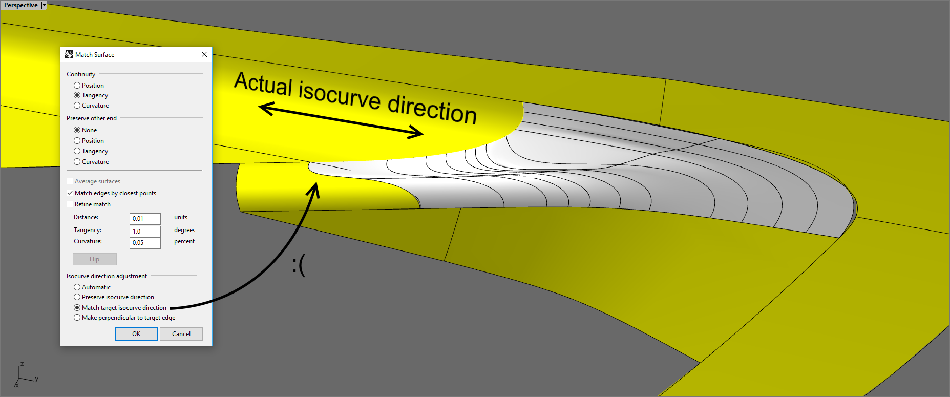
No cheating. The only time I’ve seen MatchSrf, BlendSrf, Sweep2, etc adding spans and control points “parallel” to the edge of the surface is when the additional control points are neccesary to satisfy the requested combined continuity conditions at the edges being matched and being preserved. (If MatchSrf with “Average surfaces” is used then additional control points may be added to both surfaces so that the averaging can be done.) So no cheating - it would be mathematically impossible to satisfy the requested conditions without the added control points. A different situation arises when one or both input surfaces have sufficient or excess rows of control points with some close the the edges. In that situation Rhino only moves the closest row for tangency matching and the two closest rows for curvature matching wich can cause abrupt changes to the surface. But that the user may want more rows of control points moved so that the changes are more gradual.
Added control points are added “perpendicular” to the edges when needed to satisfy the continuity conditions along the edge. When I’ve observed this happen it appears to be caused by it being impossible to satisfy the requested continuity with the input number of control points and knot vectors. So control points and knots/spans are added until the continuity conditions can be satisfied. Sometimes it looks to me like a better distribution of fewer added points which allow satisfying the conditions may be feasible but I have not verified this.
I started another thread about why control points sometimes appear to be chaotic. Rebuild to higher degree - "Chaotic" control points
This is also my finding. What I usually try out first is to insert one or more automatic knots.
The main issue is that users who aim to produce clean models with Bezier surfaces are stuck to choose either distorted rebuit surfaces (if they use the current Rebuild tool) or multi-span ones (if they add extra spans). Both methods lead to bad reflections and time-consuming control point adjustment.
1 Like
The spacebar is a little lower on the keyboard. ![]()
![]()
2 Likes
Ha-ha, nice touch! ![]() I wrote that message on my phone, so it’s very possible to mistakenly press the “B” and “N” letters located just above the space bar key.
I wrote that message on my phone, so it’s very possible to mistakenly press the “B” and “N” letters located just above the space bar key.
PS: ! _Theybusenthe may become a secret command in Rhino 9. ![]()
2 Likes
A proposal for a new tool: Bridge surface
It should be able to create a new smooth single-span surface (degree 5, 6 control points) between two surfaces, even if they are not touching together. There must be an option to change the structure of the bridge surface to a desired accuracy, but the default must be a Bezier surface (degree 5, 6 control points).
Here is a sample file to give you a better idea. The bridge surface is coloured in blue, while the target surfaces are coloured in yellow and red, respectively. If you try to apply ! _FilletSrf with about 150 or 200 mm radius, it will produce a messy result with literally unusable surface consisting plenty of chaotic control points. The goal is to build a clean surface with G2 continuity at either end at the cost of loose matching between the surfaces. An additional “Refine” option in the command line could be used to match the bridge surface more accurately at the cost of adding more spans and control points.
Bridge surface.3dm (283.7 KB)

Ideally, the Bridge surface tool should offer 3 ways to create the bridge surface:
- Ask the user to pick the relative points where the surface will start (#1) and end (#2) on each target surface. Orientation must be relative to the two picked areas. Three options must be possible here:
- “Extend” (spreads the width of the bridge surface along the entire size of the target surface);
- “Partial” (limits the width of the bridge surface just like how the “FilletSrf” tool does;
- “Adaptive partial” (adapts the width of the bridge surface relative to the opposite end).
-
Ask the user to pick two target curves on or near the target surfaces (similar to how the “OnSurface” option of the “Match surface” tool works). This will limit the bridge surface’s width to cover only the length of the target curves, so if the latter are shorter than the target surface, the bridge surface will not be build along the entire width of the target surfaces;
-
Ask the user to directly draw the approximate curves on surface by drawing with the mouse. This approach should be quite easy to implement, because it’s already implemented in the “Sketch on surface” tool (
! _Sketch _OnSurface=Yes). An option to automatically convert that curve to a loose version with fewer control points should be present, such like 6 control points with degree 5. Once the user draws the two target curves on the two target surfaces, the “Bridge surface” tool should bring a pop-up window with additional options (or they could be displayed in the Command line instead).
The additional options must also include matching orientation of each surface edge individually: Straight, Normal to curve, target U durection, target V direction.
7 Likes
Super Gumball will let you change the Drag mode with a single mouse click! The icon is context-sensitive and changes its appearance according to the active Drag mode.
Clicking on the icon with the left mouse button changes the Drag mode.
Clicking on the icon with the right mouse button reverts to the default CPlane mode.
Alternatively, you can choose whether that icon will be showed near the center of the Gumball, or it will replace the white circle currently used for “Gumball options”. In this case, the Gumball options will be accessible via holding the LMB on the icon for 1 second, whereas a quick click will change the Drag mode.

2 Likes