Hi Bobi, where is the kitchen sink icon in Gumball? —-Mark
2 Likes
What on earth is drag strength?
1 Like
This:

1 Like
Cool, I don’t think I’ve ever needed that
1 Like
Attached here is a Rhino 7 3dm scene consisting a single surface with a proposal for a dedicated “CP Gumball” (control point Gumball) for convenient control point manipulation. You will notice that the arrows are colour-coded based on the U and V colours, and oriented along the control polygon of the selected surface control point. There is also an additional blue handle for moving along the normal direction. The idea is that when the CP Gumbal is active, Rhino’s current default Gumball should be deactivated.
CP Gumball.3dm (230.2 KB)
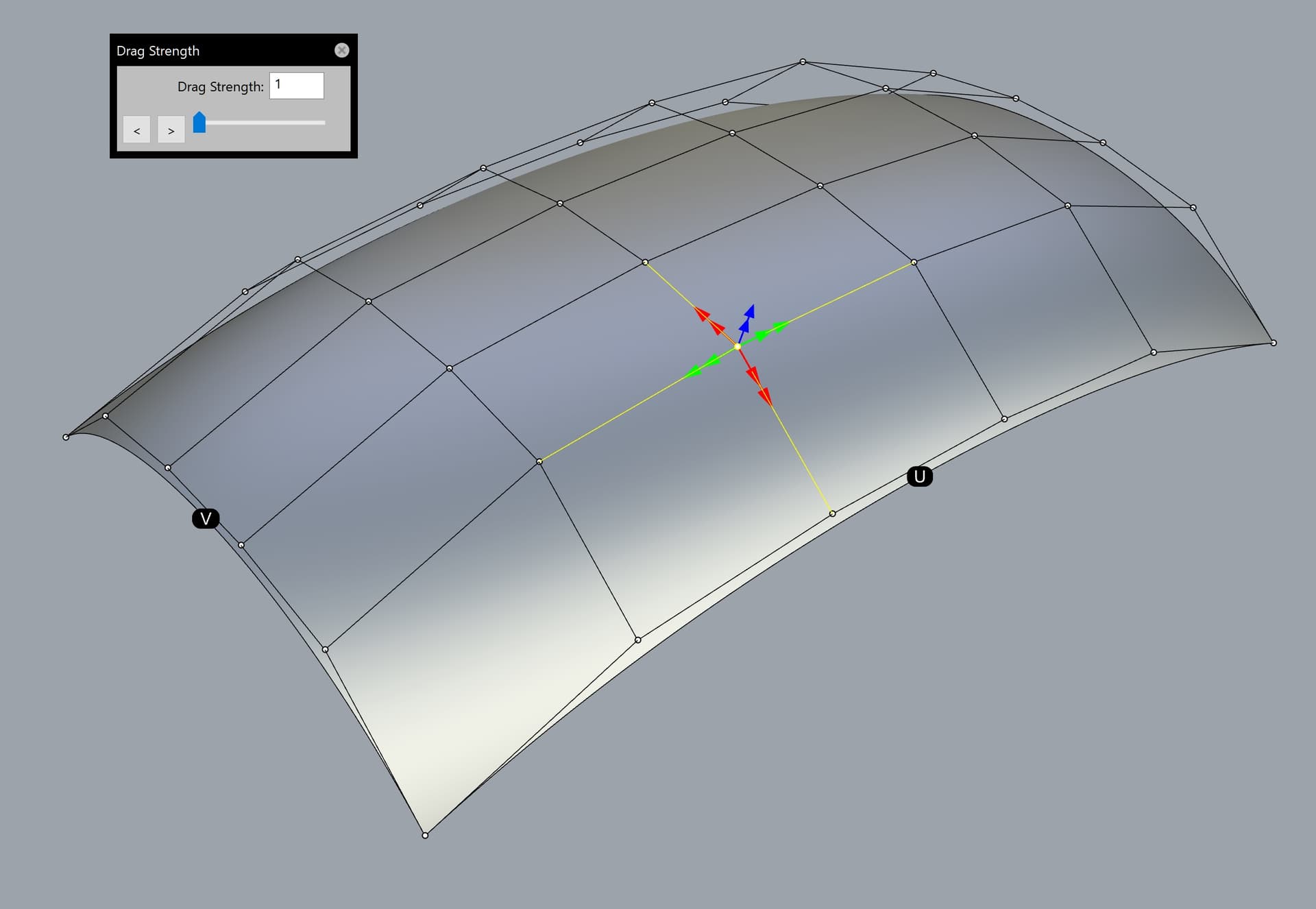
This is based on the “Super Gumball” idea proposed in my earlier posts in this topic.
Here are some more details about the CP Gumball:
-
When the CP Gumball is active, moving the selected control point will be free in any direction along the imaginary control polygon (4 flat planes based on the respective couple of control polygon vectors). Alternatively, the control point could be moved along the common average plane based on all 4 vectors of the control polygon surrounding the former.
-
If two or more control points are selected simultaneously, dragging any of them will move all control points simultaneously along their respective control polygon.
-
There are two arrow handles in any of the 5 directions. Dragging any of the inner handles will be at normal speed along the corresponding control polygon vector.
-
Dragging any of the outer arrow handles will act as a “Drag strength handle” automatically set to 5 for the current Rhino session. Note that when the “CP Gumball” is being activated, the Drag strength’s pop-up window should open automatically and be set to 5 (as mentioned above). The user could change that value afterwards. The default value could be customized from the Rhino options, in case that the user prefers any other value as a default instead of 5. Having dedicated “Drag strength” handles next to the normal speed handles will significantly improve the workflow of the users by saving time and reducing the mouse clicks.
-
“Drag strength” must be upgraded to allow entering a value lower than 1 (such like 0,1 or even 0,01), because the current implementation is too limited in that regard. Take for example the “MoveUVN” tool which has a dedicated button for up to 0,001 units, but clicking on the tiny “down arrow” against “Scale” could further reach even stricter values such like 0,0001 or 1E-14 units.
-
The user must be able to customize the size of the arrow handles (similar to the customization of the default Gumball), as well as whether the triangle arrows will include bars starting from the control point, or not (just a tiny triangle handle with no bar).
-
There must be two dots along the middle of the positive edge of any surface with visible control points, named “U” and “V”. This is self-explanatory. They could be either black with a white letter inside, or coloured in red and green for a greater visual distinction (or any other colour combination set by the user). Furthermore, these dots could be shown upon running certain commands related to UV direction, such like “Extract isocurve”, “Dir”, “Rebuild”, “Rebuild UV” etc.
2 Likes
I just added some extra text to my last post related to concerns about the “light up Christmas tree” (crowded Super Gumball). ![]() The easy solution is to simply Ctrl+click on the “Gumball mode” icon (where the white circle handle is located currently) to toggle between the blank default Gumball and the far superior Super Gumball. Problem solved with a single mouse click!
The easy solution is to simply Ctrl+click on the “Gumball mode” icon (where the white circle handle is located currently) to toggle between the blank default Gumball and the far superior Super Gumball. Problem solved with a single mouse click! ![]() Those who will hate the Super Gumball simply won’t press Ctrl+mouse click on the “Gumball mode” icon.
Those who will hate the Super Gumball simply won’t press Ctrl+mouse click on the “Gumball mode” icon.
Clicking with the left mouse button on the “Gumball mode” will cycle between the the proposed Gumball modes: World, Control polygon, UVN, View, CPlane.


Note that in my example about the optional secondary handles for “Drag strength” are only activated by holding Ctrl and clicking with the mouse on the “Gumball mode” icon (replacing the current white circle). Less advanced users who just want to use the current most basic Gumball handles don’t have to do anything.
My proposal is based on years of extensive use of various custom methods for control point manipulation in Rhino. The lack of such tools in Rhino is one of its weaknesses compared to programs like Alias. All the drag modes in the current Rhino are flawed to a certain degree and are unusable for a proper control point manipulation.
Not to mention that the “Drag strength” itself is limited to a minimum value of 1, which is not enough for a precise adjustment (especially from a longer distance where the drag strength factor is vastly increased). For example, if I work on a large surface such like car door or any other type of product design, I want to see the whole surface while using “Drag strength” at its minimum value of 1. However, since the camera is about 1-2 meters away from the control point(s), the set value of 1 becomes an obvious obstacle that will not let me apply a fine adjustment. In this case, being able to set a value of 0,1 or 0,01 would be welcome.
6 Likes
I added a new image in the post above, consisting more information about the functions of the Super Gumball.
1 Like
Another much needed improvement must be fixing the massive delay of opening the Rhino options when the display modes are a greater number. I have more than 120 display modes and opening the Rhino options panel became super slow once I reached more than 40-50 display modes a few years ago. I would rather have a delay only when I try to expand the list of display modes. Opening the rest Rhino options should not be affected by the number of display modes.
The developers don’t see this bug, because they test Rhino with several display modes only.
Another bug related to the display modes, which needs a fix in the future Rhino releases, is that upon importing a new display mode, the focus is then given to a different display mode that was not used at all in the current Rhino session! For example, lets say that I do some changes in Display mode A. Then, I import Display model B. Sometimes, Rhino will randomly expand some existing display mode, lets call it Display mode C. This is a very unwanted behaviour, because it could cause an accidental modification of the wrong display mode.
1 Like
ditto for Named Views. after more than five or ten named views, it takes ages for the panel to open because of all the thumbnails, and our workaround has been to have an empty file that’s only for setting and saving views that are synced with enscape. more often than not, the name of the view is more helpful than the small thumbnail, so an option to disable thumbnail generation in Named Views would be useful
1 Like

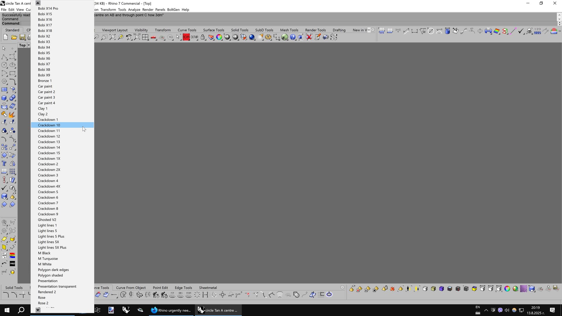
Yet another proposal related to the display modes. This time, it’s about the ability to select a display mode in a very convenient way. The current implementation is quite restricting, because the display modes are listed vertically along many other options in the same pop-up window, eventually leading to a massive frustration due to the inability to directly see and reach some of the later display modes.
The right side of the picture shows how a more convenient implementation should look like. Just below the default display modes there must be “More display modes” or “Custom display modes” menu, which could expand an additional pop-up window consisting only the names of all the extra custom display modes. Rhino should be smart enough to expand horizontally the pop-up window based on the number of display modes. For example, 20 display modes could fit in a narrow pop-up window, but 150 display modes will require a much wider window. Once the width limitation is reached, small triangle arrows should appear at the top and bottom of the extra pop-up window to enable vertical scrolling of the list with display modes.
Note that this new implementation will require far less time and mouse clicks.

That functionality is already implemented for other options inside the same pop-up window, so it’s up to the developer’s desire to enable it for the display modes, too. ![]()

Also, fix the bug that lists the display modes in an unnatural way. Currently, “Display mode 2” is shown below “Display mode 10” despite being a smaller number…
3 Likes
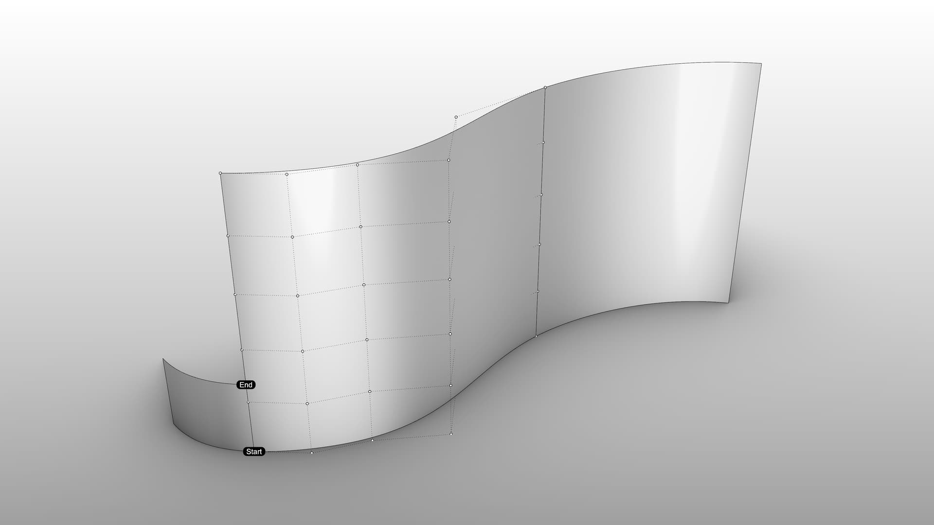
“Partial matching” is a much needed option for the “Match surface” tool. It will ask the user to pick start and end points to define the partial region that will be matched to a target edge or curve. The rest of the edge to be matched will follow the matched region in a natural way. The goal is to be able to match just a portion of the surface to be matched.
A similar approach with a partial region is already used by the ! _EndBulge tool.
Rhino could use some “hacks” under the hood to do the calculations, such like an invisible extending of a copy of the target surface edge or curve.
Partial matching.3dm (270.9 KB)

2 Likes
In addition to post #52:
Users rarely need to access the Gumball settings, so the white “Gumball settings” circle could be replaced with a dynamic “Drag mode” icon that changes its look based on which drag mode is active (World, Control polygon, UVN, View, CPlane). However, a right-click on the icon will still bring the Gumball settings. Hovering on the “Drag mode” icon will show a tooltip to tell the used which is the currently active drag mode.
IMPORTANT! Every type of secondary “Drag strength” handles could be turned on or off by the user. For example, some users may opt to have secondary “Drag strength” handles only for Move, whereas those for Rotate and Scale will be deactivated.
In case that all secondary handles are deactivated, the user could still open the “Drag strength” pop-up window to set a different value and use the regular Gumball (the current implementation).
However, if one or more secondary handles are activated, opening and closing the “Drag strength” window will NOT deactivate the drag strength value. For example, if the user activated the secondary “Drag strength” handles for Move only, opening the “Drag strength” pop-up window will set both, the primary and secondary handles for Move to use the current drag strength value. The beauty of this approach is that then the user can close the “Drag strength” window and the secondary handles for Move will STILL use the chosen drag strength value, whereas the primary Move handles will work at normal speed (100%). This way, the viewport will not be obscured by the pop-up window.
Another thing to consider is to add a button for presets (or styles), so that the user could quickly toggle between them. You may implement this by default as 5-10 different presets/styles with various parameters.
But the more preferred approach is to allow saving of custom presets, including the angle of rotation.
The presets (or styles) must store all of the current settings, so that they could be reached with a single mouse click. I think that being able to save up to 10 styles is enough for most purposes.
As an added bonus, users will benefit from the ability to save and export these presets, so that they can import them into another Rhino file, another PC (nice for companies with multiple Rhino licenses) or share with other users.
There must be buttons to create a new style and delete a new style. Exporting and importing one or multiple saved styles could be done from another icon (a gear, which is the universal icon for extra settings).
Here is a sample look of the Zebra panel including the proposals above. Note that the icon of every saved style corresponds to graphical style in the viewport (zebra stripes, points, rainbow etc).

Ideally, hovering over any of the 10 buttons will bring a pop-up tooltip that lists its numerical settings.
The main idea for the style is to be able to quickly switch between 2 or more settings, such like:
Style 1: Dots.
Style 2: Rainbow with 30 degrees angle.
Style 3: Rainbow with 67 degrees angle.
Style 4: Thin Zebra stripes.
During modeling and especially while adjusting the control points, it’s essential to switch between two or more positions of the stripes to examine the changes, then go back to the previous settings.
2 Likes
I posted this in another topic, but I include it here as well, because it’s essential for the future development of Rhino and I would like to keep my proposals collected in a common topic here.
Here is a complete 3d model of the Super Gumball, made to help the developers implement it as soon as possible. I also included two of the images used in the file, complete with text explanation of every function of the Super Gumball. There are two saved Named views that reset the view to:
- The same size as the actual Gumball as seen on my 4K screen (may appear different in your Rhino);
- A close-up view to fill the whole viewport (just like the last image below).
Super Gumball 3dm.rar (1.4 MB)
Note that I created all handles (except for the cutting line handles from Rhino 8), whereas some of them will be automatically hidden during a real usage, because they are context-sensitive. For example, the Plane handles could hide once they reach a certain rotation relative to the view. Or, the Scale handles hide when a control point is selected. You get the idea. ![]()
The settings must allow a full customization regarding the visible secondary handles, including their individual: size, thickness, visibility, distance from the primary handles. This way, the user could opt to enable only the secondary handles for Move, while keeping the rest ones hidden. The secondary Rotate handles in this example are 60-degree arcs, meaning 15 degrees shorter at either end than the primary rotate handles that use a 90-degree arc.
Right-click on a secondary handle opens a tiny pop-up menu with a quick access to 6 “Drag strength” presets (0.1, 1, 3, 10, 20, and 50), so that there is no need to open Rhino’s current “Drag strength” panel. Note that the smallest drag strength ratio is 0.1, which is very important for fine adjustment from a far distance, such like when the user wants to have a view over an entire car fender while dragging some control point. A value of 1 is way too fast in this situation.


1 Like
Another BUG that i noticed in Rhino 8 a while ago, which I also reported numerous times and, sadly, it’s still not fixed, is the behaviour of the icons on the main top toolbar that open the Layers, Properties etc. Currently, if I click on the “Layers” icon, it DELETES the corresponding icon on the vertical right panel when it’s not visible (provided the auto-hide function is active). This forced me to do more mouse clicks to enable the Layers icon again, but the other issue is that, by doing this, it sticks it to the last place, even though it was above prior that. It’s a super weird implementation. No idea why the “Layers” icon on the top panel DELETES the corresponding icon on the right panel, since the general idea of that icon for nearly 3 decades was to open the Layers panel.
My next proposal is related to the “Match surface” tool, whose “Refine” option is notorious for adding of unwanted spans as a way to match the surfaces as close as possible withing the set tolerance.
A better approach would be to raise the degree of the surface and keep the spans intact. That way, the surface will be far smoother than the current approach whose added multi-spans destroy the smooth flow of the matched surfaces.
Here is one example where the raised degree shows its advantage over the regular “Refine” option of “Match surface”.
20250826_BlendSrf_BUG.3dm (601.6 KB)
")
–
In fact, this is in line with another proposal in this topic, which is to enable rebuilding of the surface to be matched within the “Match surface” tool (and several other tools, as well). This is exactly the biggest power of programs like Alias over Rhino. Alias has “Explicit control” option for its NURBS surfacing tools that allow the user set custom parameters for the surface topology during the preview of the active command. Quote from post #1:
Also, one can have a persistent continuity locators on each surface edge, evaluating for different continuities and updating while modelling. Rhino has the math. It only needs the tool ; )
1 Like
I logged that earlier:
RH-79025 Layer and Properties buttons
1 Like
have you tried GlobalEdgeContinuity in Rhino 9?