I am the Technical Lead of LUX CAD SOLUTIONS, a specialized agency for maritime model making and engineering based in Germany.
We are looking for a skilled Rhino 3D Designer (Freelance) to support us with ongoing projects.
The Task: You will be creating high-quality 3D hull surfaces based on existing 2D lines plans (Spantenriss / Linienriss) for model ships. The ships deck is not included. The goal is to create clean, fair, and production-ready NURBS surfaces for 3D printing.
Important: Please note that the source drawings are often vintage or not 100% mathematically precise. We do not expect you to trace every line blindly if it leads to a bad surface. Instead, we expect you to interpolate sensibly and correct small inaccuracies if necessary to achieve a fair shape that comes very close to the plans intentions.
What we are looking for:
Deep understanding of Rhino: You know how to handle single span, curvature continuous (up to G2) surfacing for production.
Naval Architecture knowledge: You understand how to read a lines plan (frames, waterlines, buttocks).
Precision: We need clean topology. Curves must be fair, surfaces properly matched.
What we are DEFINITELY NOT looking for: We have had bad experiences with low-quality outsourcing in the past. We do not accept:
Messy “Patch” commands with hundreds of control points.
Wavy surfaces that look good in “Shaded” mode but fail the Zebra analysis.
“Spaghetti” curves without logic.
Bad surface matching
Visual Examples:
1. THIS IS THE INPUT: We provide complete high resolution lines plans of the hull in pdf-format like this. You need to be able to read this and translate it into 3D (.3dm + .stp)
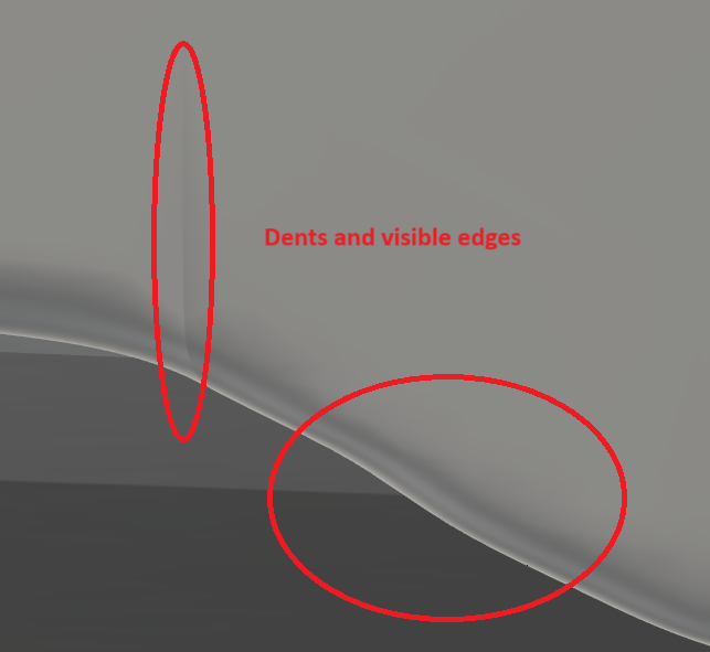
2. THIS IS WHAT WE DO NOT WANT: Please see the attached images. This is an example of work we rejected. Uneven surfaces, bad continuity, and “bumpy” hulls are not acceptable for our high-quality models.
Interested? If you know how to build clean, fair hulls and are looking for a reliable partner, please send me a DM or an email to: lukas.paustian@lux-cad.de
Please include the following in your message:
1-2 screenshots of a hull or comparable work you have modeled (preferably with zebra analysis).
Your price offer: Please state your hourly rate or better a fixed price estimate for modeling a typical hull based on plans like the one shown above.
Your availability: Can you meet a turnaround time of approx. 2 weeks?
Do you provide tables of offsets or only lines drawings? Any idea of the amount of possible distortion of the lines plans you provide compared to “as drawn” due to distortion of the paper from folding, rolling, humidity changes, reproduction, scanning, etc.)?
Are photos of the vessels also available? My experience is photos can help fill in the gaps in the knowledge of the hulls shapes.
What are the general tolerances for differences with the lines planes?
How will the 3D surfaces be used? For renderings with “perfect” reflections? For engineering purposes? The level of refinement can significantly influence the time required. An example of an acceptable surface would be helpful.
Thank you for these constructive questions – they help to clarify the scope significantly.
To answer your points:
Input Data: We provide high-resolution PDF scans of the line drawings. We do not have tables of offsets.
Accuracy & Interpolation: Since these are vintage plans, distortions (paper shrinkage, scanning artifacts) or inaccuracies in the original drafting are expected. Possible distortions might be up to a few millimeters on some plans. Therefore, we explicitly expect you to interpolate as stated above. We trust your judgment to prioritize a fair curve over a wavy line on the PDF.
Photos: Yes, photos of the original vessels are usually available and will be provided to help interpret complex areas (like the stern/wulst).
Tolerances: We prioritize a fair surface over millimeter-perfect adherence to a distorted plan. For a model hull of ~50cm length (scale 1:50), a local deviation of 2-4 mm is acceptable if it helps to achieve a clean surface flow and captures the appearance of the hull.
Usage: The files are used for FDM 3D printing. The customers will sand, fill, and paint the hulls, so we do not require “Automotive Class-A” perfection regarding light reflections. However, the geometry must be watertight, visually fair (smooth), and free of visible dents or hard kinks (G2 continuity preferred where possible) since the customer views it in CAD software.
The ‘bad example’ I posted earlier simply had too many visible dents and continuity breaks, which is what we need to avoid.
Here’s a rendering of antoher hull that’s ready for shipping:
Wow Lukas, this sounds like an exciting Projekt!
I would be very interested- but the next 2 weeks is very tight with other projects…
(my background is in 3d modeling for Industrialdesign and automotive- for 15+ years)
is the example Drawing the actual Model that needs to be done in that timeframe? Or is it just an example for the scope and level of detail?
Again I would be quite interested- but i think the deadline until xmas is a bit unrealistic for me.
If this extends/continues in the new year- I would love to join.
Grüße, James
This sounds like an interesting project. Clean single span NURBS with proper G2 continuity is the only way to get production-ready hulls that actually hold up under zebra analysis.
Would be happy to discuss further and share some relevant work samples if you are interested.
I have time for you to create fixed price in 2 weeks (rate 90 hours) 3d model of your pdf without issues you mentioned. I send you already an e-mail yesterday. Regards Bernard Kuipers. www.b71.eu or www.b-71.com or www.interieurarchitectbernardkuipers.com
I want to thank you all for the overwhelming response and the high quality of portfolios sent to me. It is great to see so much talent in this community and the help I’ve received so far.
We have successfully found a partner for the initial pilot project phase and are now working to make it happen. Therefore, we are closing the application process for now.
I have received many messages and will keep the contact details of suitable candidates in our freelancer pool for future scaling. If you have already emailed me, I will get back to you, but please understand that I cannot accept new applications at this moment.