Here’s my very first attempt lofting a ship hull using control curves.
I’ve drawn the bow rail and attempted two stations. Can someone have a look and see if I’m heading in the right direction, Any advice would be greatly received, please remember I’m completely new to Rhino 5.
I watched the rapid hull modelling video, looks very easy , but I think its going to be much more difficult than it looks…lol
I was hoping for a response to my last post regarding the modelling of a ship hull in Rhino, anyway I’ve been working some-more this afternoon on the model and would like someone to have a look over the file and give me a few pointers.
As mentioned before I’m completely new to Rhino, I had a look at the post on Rapid hull modelling, looks great but theres no instructions in how to perform this method. If anyone can point me in the right direction i’d be extremely grateful.
There wasn’t much in that file that you posted. 3 curves and 3 planes that didn’t contain the reference pictures.
At any rate, just by checking the link that I posted in your first thread, I see that there are several videos available. There’s also a PDF and example file. Did you go through these?
Anyway, here are more links with information. RhinoCentre also published a grasshopper definition that you could adapt and use.
@m5currie It is difficult to respond without some understanding of your objectives.
Are you trying to create an electronic model of an existing design, a derivative of an existing design, or an all new design.
If you are trying to create a model of an existing design or a derivative of an existing design what are you starting with - lines drawing, table of offsets, simple outline/arrangement drawing, photos or something else?
What will be the use of your electronic model - design of a new vessel, school project, build a scale model, ???
Thank you for the replies earlier. Since the last posts I’ve spent a few hours closely examining the rapid hull modelling method and have redrawn the control curves, I’m sure there not perfect but its a start nevertheless.
I’m planning in making an exact model of the hull from the lines plans that are embedded in the file. I will thicken the hull to 3.0mm and have her printed in 4-5 sections then bonded together to be built into an RC model. I want the hull to be an exact copy of the original trawler.
one of the features that must be re-created exactly is the flat side of the vessel with the leading edge contour. I’ve attempted this by creating a curve that starts from the keel towards the bilge, round the bilge up onto the side and then leads upwards and forward towards the bow top rail, i’m not sure if this has been done correctly.
I’ve also tried to use only 7-8 control points where possible, trying to keep that number the same in each curve. I may need more practice at this, but for someone thats only started using Rhino 4 days ago I’m fairly pleased with the progress so far, just need some guidance.
I’ve attached the latest version for someone to have a look at.
Here is a file showing how to use loft for this hull. The bow is made using loose loft and the main hull is a normal loft ShipHull.3dm (144.3 KB)
It is a good idea to make curves that match. That is most important if you are going to use loft to create the surfaces. You need to understand that just making curves with the same number pf points is not enough to make the curves matching. The knot structure needs to match also. In the file I made all the curves as copies of one curve (your original curve at the bow). That guarantees all the curves will match.
I would recommend that you use as few planar stations as possible to create the basic shapes.
If you have simple surfaces with few control points it becomes possible to point edit the surfaces to refine the shape. You can use history to project other curves into the surface to use as guides for refining the shape while point editing. You can also use curvaturegraph as a guide to help keep the hull smooth when editing.
Thanks fort the file you uploaded here to the forum, I had a good look at it and it makes perfect sense. I agree with your comments about the knot structure in each curve. I went had a look again at the Rapid Hull modelling file and can see that for each curve the control points are pretty much similar in position to each other throughout the whole model.
I’ve deleted my initial curves and will start again from the bow curve working aft. I have attached a screenshot of my bow curve with the curvature graph, can you have a look and give some feedback on its properties, does it look smooth and would you call it fair?
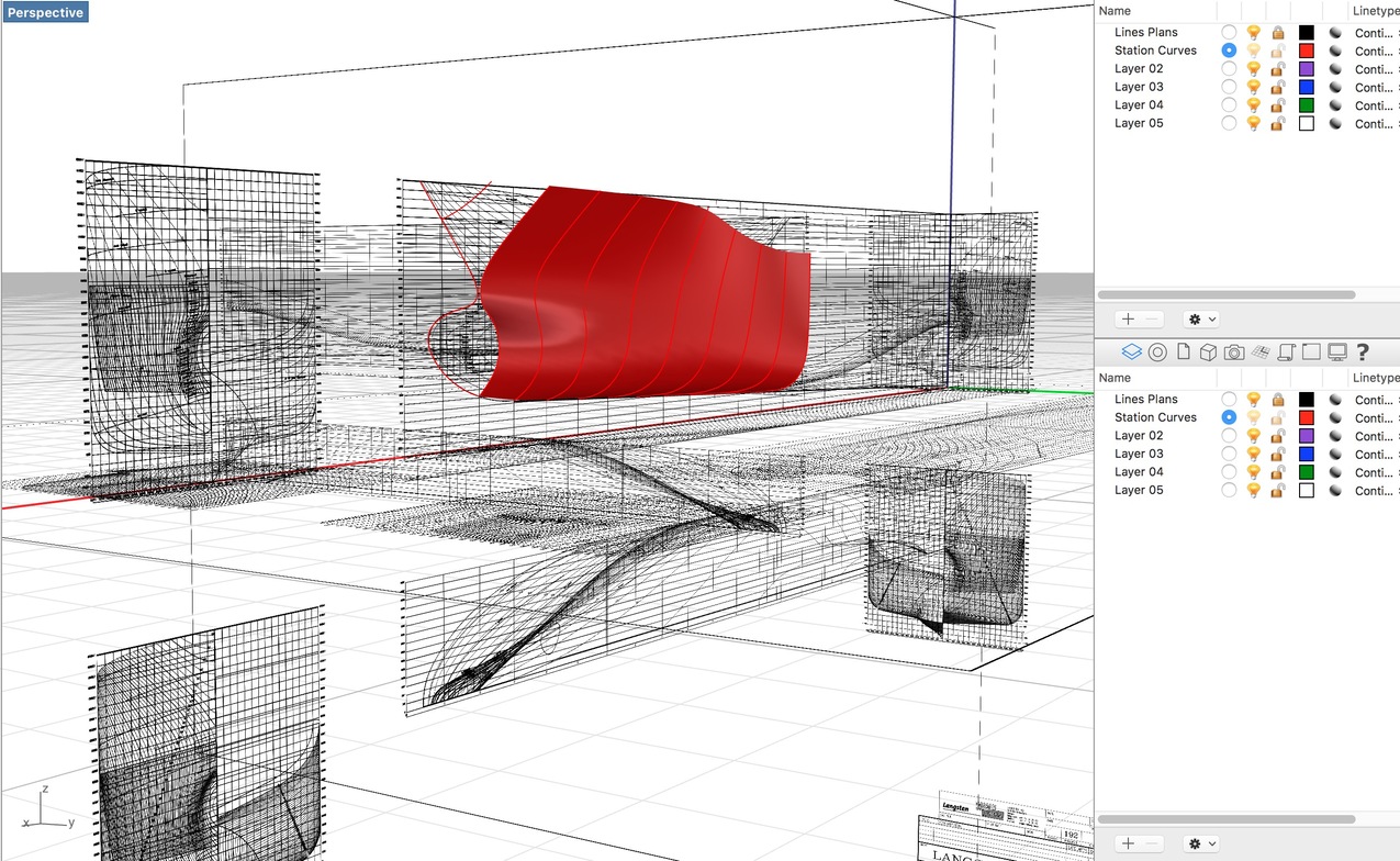
I’ve uploaded a file with new curves to help shape the hull of my trawler, I have tried my best to contruct the aft curves following your guidance received earlier, first impressions when lofted that the aft section will only need the absolute minimum amount of tweaking to get the correct shape. Just got the bow curves to complete.
However when i loft the hull and look down the length of the hull from bow to stern i noticed that the hull is a little shallow in the middle around the midship frame, the curves are drawn following the deepest frame… I’ve attached a screenshot of the issue.
What would cause this? Also I haven’t lofted this file its just the curves( cant seem to undo the history after saving to allow me to edit the curves)
I think what you are seeing there is just the coarse render mesh. You might want to set the angle tolerance in the mesh settings smaller or just use a very large number of minimum starting quads.
You have done pretty well at making curves that match well.
If I were doing this I would try to make the profile curves as close to parallel planes as possible and more evenly distrubuted. That will make it easier to keep the hull flow lines from being wavy and bumpy. ShipHull2.3dm (79.7 KB)
Also if you are going to make this all one surface including the bow , I would make the bow so that it extends a little past the centerline and then trim it back to the mid line and then use Mirror for the other half.
Thanks for the feedback Jim, much appreciated. I’ve been working some more on the model and will extend the bow beyond the centreline as you mentioned.
Yesterday I experimented with the thickening using the offsetsurf command and noticed that the bow area would need trimming prior to being mirrored and joining the two halves of the hull so extending it would help in creating a nice face to join the other side of the hull.
I was looking at the render mesh settings, don’t quite understand how to change these settings, still very much in the beginners mode here in Rhino.
I could see clearly what you mean about distributing the profile planes more evenly. when I get the rest of the bow section profiles in place today I’ll look at the distribution. I’m currently focusing more closely on the knot structure and using the curve graph to smooth things out some more in the profiles.
The simple settings are just a slider - you want a denser mesh so that it more accurately represents the NURBS geometry.
There is good information on mesh settings in the Help for the detailed settings(hit F1)
Did you happen to use the “loose” style when you lofted the curves? The loose option produces a smoother surface but the surface does not pass through the profile curves. The “normal” loft is what you want to use to get the surface to be exactly on the profile curves.
You might try lofting the curves with history turned on. You can then move points on the profile curves and see what it does to the surface. You can also use curvatureGraph on the surface since that is the curvature that counts in the end.
I do not agree to use the normal loft as it will result in hours on fairing. Use the loose loft method means that some of the loft curves will be outside the final hull, pulling the surface to the required place. Only the last loft curves and maybe the midship section curve will be on the final hull shape. Loft the whole vessel at one go with record history on. Use less loft curves as is mentioned in the pdf tutorial Powerful Ship Hull Design in Rhino with Rapid Hull Modeling Methodology.
As the final shape should match the original linesplan , do the following: create ribbons (Rhino function _Ribbon) on some of the original curves, per curve one red to the inside and one green to the outside. Make the height of the ribbons a certain percentage of the breadth. Now you can play with the loft curves to match the ribbons.
Who are you not agreeing with? I was explaining the difference between a loose loft and a normal loft, A normal loft will produce a surface that the curves lie exactly on the surface. A loose loft the surface will not pass through the input curves but the surface will be smoother.
It is not impossible to get a fair surface with a normal loft but looking at curves in the picture you posted lofting curves that are organized like that will likely produce a very messy surface using normal loft. With curves arranged like that the only hope for a manageable surface is to loft with the loose option .