Hello,
I am trying to understand CPlanes. I have 2 buildings in a model, with differing front alignment angles. I want to create Layout Details for each building, with each orientated to the relevant angle. My understanding is that the trick is to activate a Layout Detail and set the relevant CPlane, then set the Camera to the relevant CPlane Front or Right elevation.
On the Layout page, the left Details relate to Building A on the World CPlane. The right Details relate to Building B on the TS CPlane.
The lower right Detail shows the Right image aligned correctly to the TS Plane, although I had to select Camera CPlane Top.
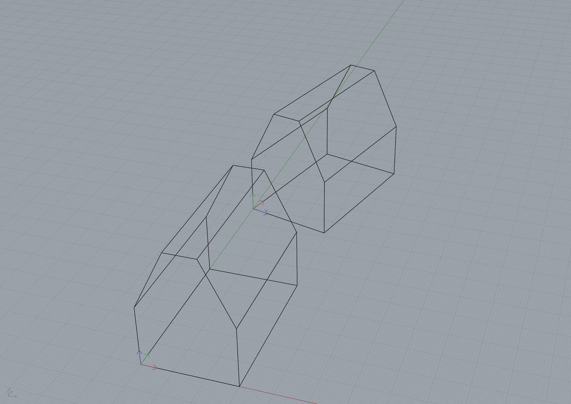
In the Perspective view, I note that the TS CPlane lines are red and green for X and Y, but the arrow colours are confused - red instead of green, blue instead of red, and green for Z.
The upper right Detail is intended to show the Front image, but it only shows when I select CPlane Right or CPlane Left, and then it is rotated at 90 degrees.
CPlanes01.jpg was captured after activating the World Top CPlane, and it shows 2 sets of coordinate arrows, with colour confusion. CPlanes02.jpg was captured after reactivating the TS CPlane, and it has removed the World coordinate arrows.
I am seeing similar results on Windows, so it is highly likely that it is due to my misunderstanding. I have watched some videos and hunted through the documentation, but I have not found the magic.
I used TiltView -90 to rotate the upper right Detail after attaching the model.
After reopening, the duplicated coordinate arrows disappeared.
I think I have found the magic. I created a Named View in the Front view after activating the TS CPlane. I then set that Named View in the Layout Detail. Fingers crossed.
Regards, Garry.
KDRCPlane.3dm (3.8 MB)

SystemInfo.txt (5.1 KB)


