The latest Rhino 8 WIP provides for creating reflected parallel projection viewports. This is done by changing the projection for a viewport or detail to “Parallel Reflected” in the properties panel.
The lower left viewport in the following image is a Top view with TestReflectedViewport applied.
I hope there’s a way to maybe organize them in the side panel while having options to tweak their parameters. For instance, say I want to change the cutting elevation of the reflected plan from 1.2 meters from the base reference level, to 1.5m. Also having options to tweak view extents should be made. I’m basically requesting Revit like features Their RCP system is really good. If this is done well i’d skip revit for all of my 2d drafting needs.
It would be good if you could provide feedback on the feature as it is implemented. We’ve had years of users requesting the feature without ever getting a good specification to actually build that feature on - and often getting conflicting wishes. For instance, there is no “cutting elevation” at all in the feature as it is available in the WIP now. There are no parameters to tweak. If you require cutting, you just have to create a clipping plane where you need it.
If you could provide a 3dm file with a model and the expected RCP result, we’d at least have something concrete to base development on.
-wim
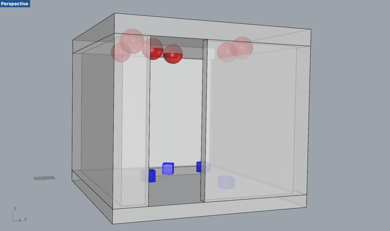
I hid the ceiling and the spheres to make a make2d in a basic Top view. Then I unhid everything and hid the floor and boxes to make a make2d in an inverted Top view using this new command. The results are here:
All works well: the geometry is displayed correctly, the “door” in the “room” remains in the same position, so you can read the two plans side-by-side. I tested the same processes using a clipping plane instead of hiding geometry - all work well.
I do encounter some gremlins not allowing me to select objects in this inverted view. Also, the blue boxes and red spheres are visible through the floor and walls in a shaded view, when they should be hidden.
Thanks for trying this and for letting us know that this generally works as required!
I’m also seeing some gremlins but not what you are reporting. Are you working with layouts or is this all in model space? Also, please run the Rhino SystemInfo command and copy-paste the result here.
Thanks!
-wim
I’ve created the following for these issues: RH-67047 - Display: Select objects in parallel reflected viewports RH-67048 - Display: Parallel Reflected projection makes objects transparent
Thanks for your feedback on this!
If all goes well, tomorrow’s public WIP will have a Parallel Reflected projection option in the properties of a view and the test command is no longer needed:
Also wanted to chime in and say thanks for this! I finally had a chance to use it, and it went very well. I will say that getting it set up felt a bit unintuitive, I think mostly due to how I’ve been faking RCPs in the past (setting view to bottom then mirroring) so I initially thought the parallel reflected setting would mimic that process, but having used it a bit, I don’t think the approach taken is at all unreasonable, I just don’t know how discoverable it will be.
I think what I would really like to see accompany this is a process for easily making an RCP from an existing plan detail. Something like a MakeReflectedCeilingPlan command where when called you could select an existing detail (and any layout space objects that went with that detail), then copy that and let the user place it where they want. The command would then look at what clipping planes* were affecting the original detail, uncouple the original clipping plane from the RCP detail, copy that clipping plane (and maybe give the user an opportunity to name the resulting clipping plane during the command so it doesn’t get lost amongst all the other clipping planes I invariably have floating about), flip it, then apply that to the RCP detail. It would be nice if this also worked on multiple details at once as well, so if you had a plan that was a couple of details put together (due to change in cutting plane or other cheat), the process would still work.
Thanks again for the RCPs! It is really, really helpful and saves a LOT(!!!) of work.
Sam
*Clarifying edit - if multiple clipping planes are assigned to the plan that is being converted to RCP (this happens more than I’d like to admit, I copy a plan, then just apply another clipping plane further from the camera, never uncoupling / deleting the first), only the furthest from the camera should be used for the RCP copy, all others should not affect the RCP copy at all. I have no idea how you would handle this test if the clipping plane isn’t perpendicular to camera. Maybe which ever is furthest from camera as they intersect the camera - target path.
I got a chance to play with the feature and it is really nice, I find the best use for it when Generating Reflected Ceiling plans for Architectural Drawings and Studies without the need to visit the Make2D workflow. However, this triggers the need for additional Clipping Plane Requirements to make it a fully functional feature in RealWorld practice.
1- Ability to add multiple clipping planes and each one is assigned to region. This is important for showing up plans for stepped plans like Theaters and Auditoriums. Also, most buildings have variable ceiling heights per floor. I’m still not sure how to implement it but it seems a necessary feature to complement the reflected plan feature. Maybe the ability to have the clipping plane either a) infinite"Default Behaviour" or 2) limited by a closed planar curve.
2- The ability to control the visibility of Items behind the cutting plane. for example, my Lighting layout plan will show a dashed linework for the furniture and casework below, this is what probably a good architectural ceiling plan should show. I think this feature can be implemented in the Clipping plane dialog below:
*** Note: The image above is Fictitious and it is not part of Rhino WIP
I know I probably need to taper my expectations, but I’m sure one day this is going to happen. Imagine we can do stuff like these when you can show your building as a whole as well as focus on a specific area.
Sorry but no. We are not adding new features to Rhino 7 at this point in the life cycle of the product. There are also several bugs and wishlist items to deal with for RCP display that need to be tuned up for Rhino 8.
Hi! I’m just noticing that this has been implemented It seems like there are some strange things going on with ambient occlusion views and normals? Its as if we are inside this cube looking at its base from behind, so the inset letters appear to be proud. Is there any way around this? Or does ambient occlusion not work with this mode?


 Their RCP system is really good. If this is done well i’d skip revit for all of my 2d drafting needs.