I have a curve (a) placed in continuity of curvature with the surface, ending in a point P on the surface.
I would like to join the curve at point P with a curve on surface with continuity of curvature (G2).
Execution: “blend curve” (curve (a) to point P, with continuity G2).
Then I use the “Pull” command.
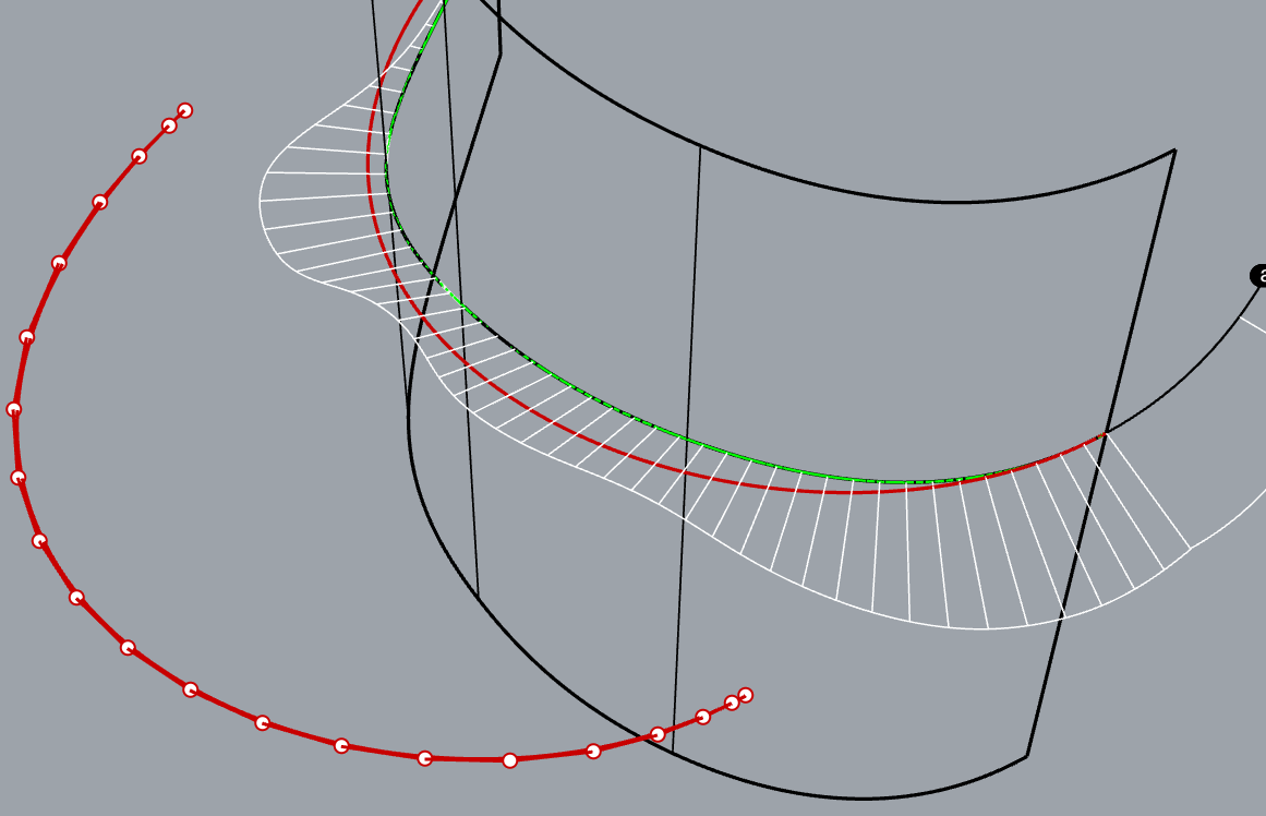
By checking the continuity of the curves by means of the “Gcon” command, the red curve is obtained in continuity of curvature (G2), while the blue curve shown on the surface has continuity of tangency (G1).
The operation with “Pull” has lowered and then changed the continuity, from G2 to G1.
Question: “Is a geometric/mathematical limit? A limit of Rhino? Or is it a normal aspect for any Cad?”.
If I remember correctly, using Catia several years ago, there is a command developed ad hoc “Blend curves on surface”, which allows you to combine in continuity choice (G0, G1 or G2) a curve with a curve on the surface without having to perform an operation projection (pull).
I believe that the chosen continuity was preserved …
Its more of a matter of a limit to your understanding of continuity and whats important and what’s not important.
The blue curve that you created is not C2 continuous internally. That internal discontinuity is a far more serious problem than the small continuity difference between the black curve and the blue curve.
It is possible to make a curve that is for all practical purposes the same shape as the blue curve and is both internally G2 and G2 matched to the black curve. The green curve in this file would be an example continuity.X.3dm (42.7 KB)
I’m trying to understand, do not get angry!
The blue curve was created by projecting the red curve on the surface with the “pull” command.
Could you explain to the less experienced how did you do it?
I think it’s enough to use a match curve in order to get a G2 continuity between the curves; but I ask: The command “pull” is normal that changes the continuity (it should not or could maintain it?).
RemoveMultiKnot will get rid the internal discontinuity. That’s all you should be interested in That’s far more important than the continuity you are worried about.
As I demonstrated the difference in shape between G1 and G2 is insignificantly small. You would never be able to see the difference on a manufactured part.
Another possibility is to InsertKnot > Automatic a few times on the red curve and pull it ‘Loose=Yes’. The result is internally smooth (especially if you change the degree to 5 beforehand) and pretty close to tangent to the black curve, and, well ‘prettyclose’ to the surface.
Thanks Pascal, your solution is better (the projected curve of grade 5 has a very good continuity, very smooth), even if the continuity between the pull curve and the black curve one is of type G1.
Better than that you can not get, right?
Pascal, ask: if you do a “match curve” I would get a continuity between the curves of G2; in this case the curve maintains the condition of belonging on the surface?
If you want the simplest curve that matches exactly and lies on the surface exactly then use extractIsocurve and edit the last 4 control points to connect the curve to point P.
In this file the cyan curve is the isocurve and the green arrows show how the points were moved to create the magenta curve. continuityX2.3dm (40.1 KB)