You may be able to improve this issue slightly by adding guide curves, but in general the quad remesher will not give singularities that line up, except maybe for some quite simple surfaces.
Sadly a quad mesh is not the same as a coarse quad layout or ‘semi-regular’ quad mesh, and generally going from the former to the latter is wicked hard.
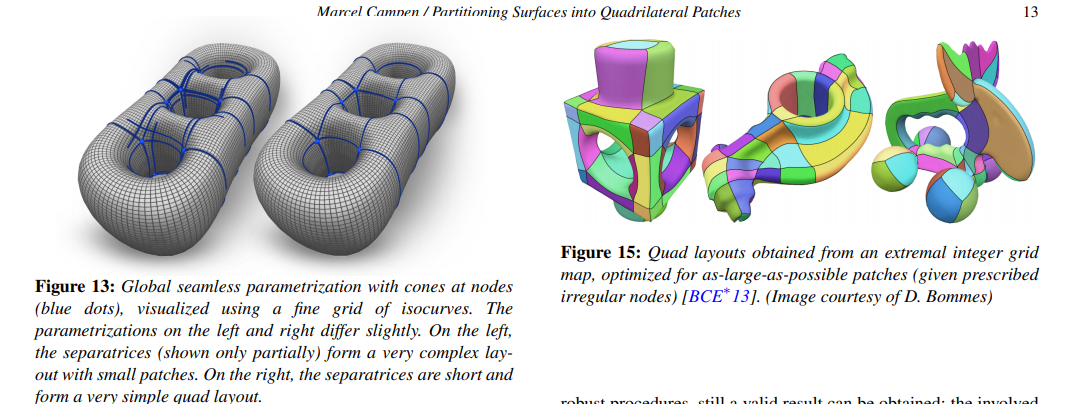
I find this a good description of the different types (from this paper):
Roughly speaking, quad-meshes can be classified to four categories with the descending regularity:
- Regular quad-mesh: all the interior vertices are with topological valence 4, there are no singularities […] The regular quad-mesh has strong topological restriction, we can never construct regular quad-mesh on the high genus g > 1 surface.
- Semi-regular quad-mesh: The separatrices divide the quad-mesh into several topological rectangles (a topological disk with four corners on the boundary), the interior of each topological rectangle is regular grids.
- Valence semi-regular quad-mesh: The number of singularities are few, but the separatrices have complicated global behavior, they may have intersections, form spirals and go through most edges.
- Unstructured quad-mesh: if a large fraction of its vertices are irregular. For example, one can convert a triangle mesh to an unstructured quad-mesh by splitting each triangle into three quads by connecting the edge center to the face center.
edit - here’s an illustration I made of these types 1 to 4 from left to right:
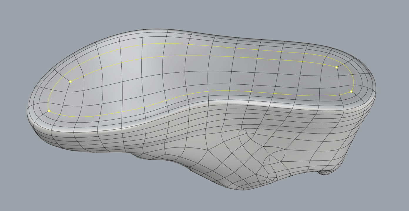
The red curves trace what are called the
separatrices out from the yellow irregular vertices. The 4 sided regions enclosed by these always have a simple grid topology, like a single untrimmed NURBS patch. For the type 2 these connect directly between the irregular vertices, and split the surface into a few large simple regions, whereas for the type 3 they spiral around so many times they end up covering almost all the edges, splitting the surface into many small regions, including many which are just a single face, or a strip one quad wide.
The quad remesher gives a type 3, but there’s no really easy way of going from this to a type 2.
There are some strategies developed for singularity matching, or sorts of ‘zippering’ surgery to do this.
I’ve looked at a lot of these, and perhaps the most promising I’ve seen is this one. One could maybe even apply some of these chord collapse operations manually.
However, I think these zippering methods can become quite complex and problematic in themselves, and they still might not give the best singularity arrangement, to the point where one has to question whether it is better instead to try a different approach to the initial quad meshing that guarantees a type 2 (perhaps accepting more manual interaction, such as user designing a coarse layout, then subdividing and fitting it onto the input surface).
By the way, this challenge is not unique to Rhino - I don’t know of any commercial software that can reliably convert a surface of any shape and topology into a simple and clean coarse quad layout in a fully automated way. This is a topic of ongoing academic research though, and I am optimistic that some day such methods will be widely available.