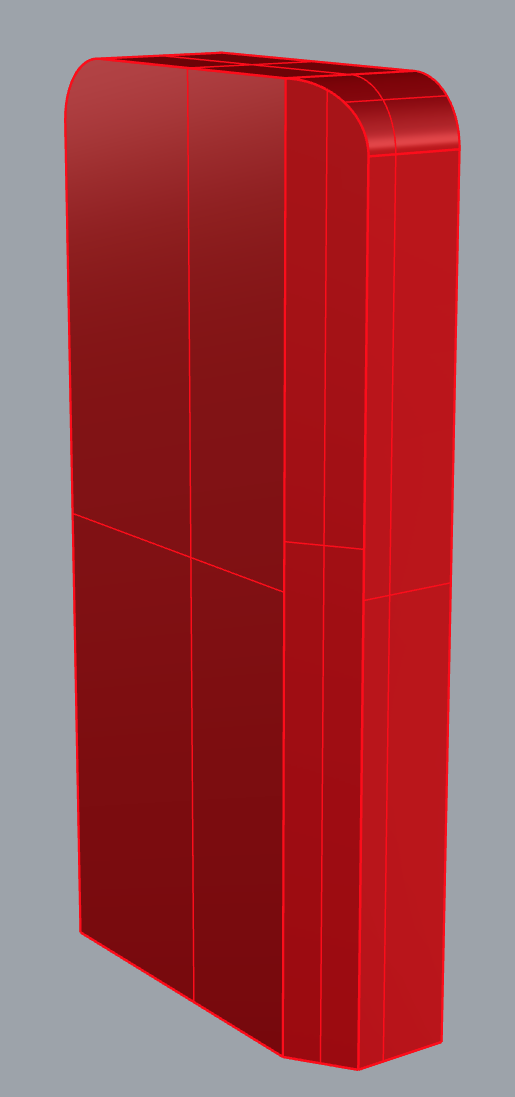
This box was made with Box and two of the upper edges filleted with FilletSrf.
Now I want to chamfer the edges (distances 9.6 at the big surface and 6.25 at the small). I want the chamfer to continue around the rounded “corners”.
As you can see, I didn’t succeed.
Thank you very much for your kind reply. Unfortunately, it’s not the trim, that’s my problem. I think that I didn’t express myself clearly.
I want the chamfering to swing around at the corner, continue along the upper edge, swing around the other corner, and go down the opposite side of the box. So that the front surface is framed by this chamfer.
Getting the chamfer to swing around at the corner is my problem.
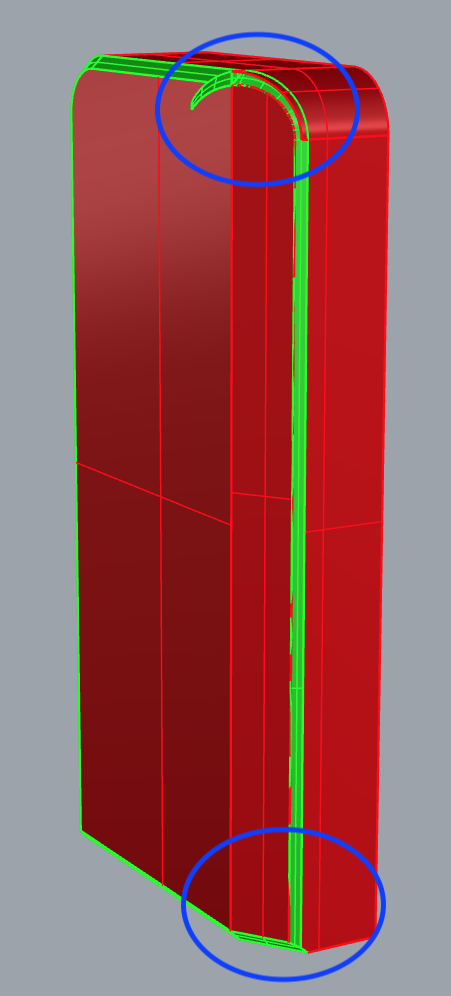
If it does something like this that means that you need to correct it manually. It did the best job it could and provided some guide geometry (green).
First explode the geometry to be chamfered. I usually prefer to place the chamfer guide geometry on a separate layer first or save selections.
Now most of it is pretty straightforward to fix. It simply boils down to going around and trimming individual polysurface faces (red) with the green guides selected as cutters, expect two edge cases, which won’t trim right away. Oftentimes the geometries are not intersecting everywhere.
The bottom one is an easy fix. The top one in this case too, however situations like these can be tricky at times.
What you want to do is extend relevant surface edges of the chamfer geometry (green) to make it intersect the red faces that still need trimming more favourably.
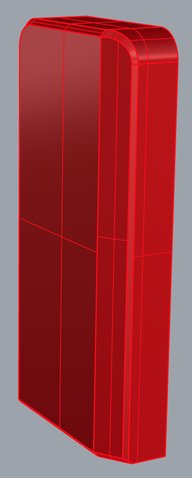
Once you have a clean chamfer perimeter/loop for the red geometries, you can proceed to clean up the green chamfer guide geometry. Surfaces that you extended for the latter, need to be trimmed back and superfluous surfaces that don’t make sense - if there are any -, deleted.
Sometimes, it’s not so easy and you can’t manage to trim back the guide geometry somwhere or it’s simply not a great fit for a certain situation.
If the situation has clean perimeter - is a hole -, you can delete the relevant chamfer geometry piece and reconstruct it with a 2 rail sweep (with 2 sections) or a network surfaces. When using a sweep it is important to use all the edges of the perimeter in the operation and no rebuilding or resampling, otherwise the geometry may look good, but at the end you’ll be unable to get a closed geometry.