I’m new to Grasshopper; I have some experience in BIM (Autodesk Revit, Tekla Structures), and I’m intrigued by Grasshopper and what it is capable of, so I’ve decided to try and learn and see how far I can get. So far, I’ve watched the introduction videos from Grasshopper3d.com (David Rutten), read some tutorials, and tried a couple of definitions.
As an exercise, I’m trying to replicate the structure of an earlier project in our firm (I work in an engineering and architecture company). We received a DWG-file with a top view and side view of the centerline (reference line) of a ride in an amusement park. Positions of all other structures (left track, right track, supporting beams, …) are all based on this reference line. (At the time of this project, another company modelled these structures, from which point we could start with engineering). My goal is to create Tekla Structures geometry based on my Grasshopper definition.
But first things first, I’ve gotten as far as this:
measure coördinates of points on reference line in the DWG
create these points in Grasshopper (I’ve created all points seperately)
between start and end points of bends, I generate a number of points with Evaluate-components (X and Y with formula of circle, Z with dividing the heigth in a number of steps)
start and end points of straight lines, and all generated points in bends are grouped, and then a polyline is created from them
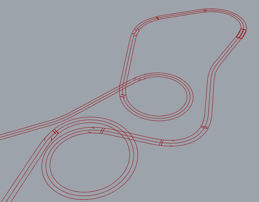
after using offset on this polyline, I notice strange effects, particularly where bend becomes straight, or vice versa. The reference polyline looks good, the offsets don’t
What am I doing wrong?
Hints on how this workflow can be improved? (I’m guessing what I’m doing is far from efficient)
Later… I fixed that anomaly by sorting one of the sets of points by their ‘Y’ coordinate, but this is not a universal solution. Better to figure out why they were mixed up?
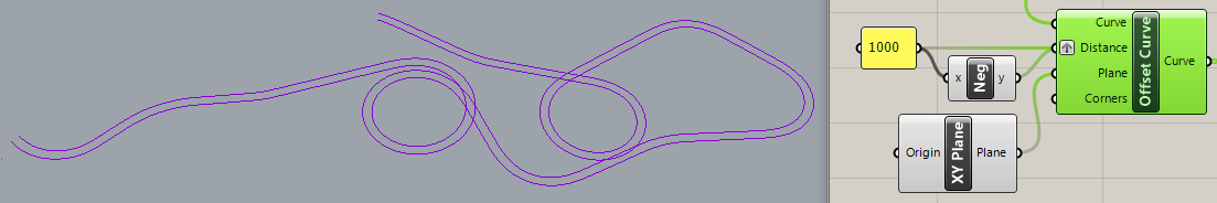
Then I noticed that the offset curves were broken into segments on the “outside” curves, so replaced the standard Offset curve with the Clipper plugin PolyOffset which produces both offset polylines from a single ‘D’ (Distance) value. But that doesn’t work well at all!!
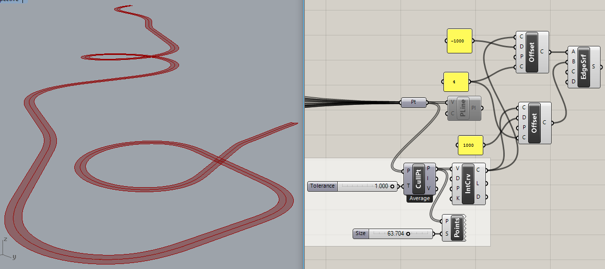
Next, I tried replacing PLine with Interpolate and immediately noticed different anomalies that suggest duplicate points? But CullPt removed only one point out of 442 and didn’t fix the problem… until I numbered the points, saw the duplicate points and increased the CullPt ‘T’ (Tolerance) value from ‘0.1’ to ‘1.0’, which fixes the problem!
I have an explanation and fix for the points being out of sequence. It’s because of the sequence in which the wires were connected to the Pt param component. That problem can be avoided by using Merge to explicitly define the sequence:
Yes it seems more complex, but I prefer doing it this way when working with complex curves due to accuracy issues (see the distance between two lines), also I can then easily manipulate the distance between curves, since the “Offset” component works much slower (but maybe it is just my pc)
Any ides how to be more efficient here and fix the issues will be much appreciated
At the risk of sounding argumentative, I don’t think these reasons stand up to close scrutiny. The accuracy issue is distorted by your measurement method. You are measuring the lines you created for lofting and they are all identical in length - that’s no surprise. A more accurate measurement is the distance between the two closest points (one on each curve) to each point on the center line:
As to the Offset component, your method already relies on using it once so what’s wrong with using it twice? As to the ability to “easily manipulate the distance between curves”, that’s trivial. And the same measurement of accuracy yields very good results:
First thing I did when I read @Joseph_Oster 's reply was learn more about lists and data trees… This indeed could have prevented a LOT of unnecessary work. Part of my learning process, I guess
Duplicate points probably come from using a wrong workflow, but I know where I went wrong on this. (If someone else somehow wants to know more about my mistakes, I’ll elaborate, but I won’t bore you with the details now).
I’ll test all of your solutions and let you know how it goes!
I made a mistake in this code I posted yesterday. Instead of connecting both offset curves to Graft, I used the centerline instead of the original Offset curve. Fixed below: