I’m new to Grasshopper, but loving what I’ve learned so far… My intention for learning grasshopper is to be able to program my 6-axis robot to machine post and beam joinery so I can make natural buildings cheaper and hopefully increase the uptake of ecological building methods.
What I would like to be able to do in grasshopper is paratmetrically create the joinery required, initially mortice and tenon, for two equal size timber members meeting at variable angles.
My initial approach will be:
do a boolean intersection operation to create a mesh of where the timber overlaps
do some grasshopper magic on the resulting geometry to divide it into two parts.
I’m guessing there are two ways of creating the join - one is with a lot of math equations, the other using a model of a joint and scaling/rotating/projecting it onto the boolean intersection mesh…
If anyone has any advice it would be MUCH appreciated.
Hi, first of all why using meshes? Since you are dealing with none curved shapes Grasshopper surfacing capability’s are totally sufficient. There are various advantages for using Nurbs data.
I have no idea on how those joints work on any angles other then 0 or 90 degrees, but I’m guessing that a rotation would be sufficient here. I believe you can do a lot of this by using boolean operations on transformed joints. Why just not starting it then, and after you have found it feasible you then might ask on how to generalising this approach which is completely different task in my opinion.
No real reason, just what I’m used to from doing game dev way back when… I’m also new to rhino… so I know I’m setting quite a challenge for myself, but I’ve got a LOT of free time and I am kinda stubborn… I’ll go with whatever works best.
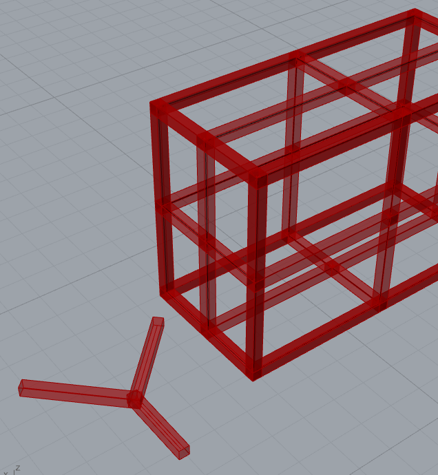
See the pic below for an example of the kind of joinery I’m talking about.
Thanks for your advice. Starting with something simpler and iterating from there is a good approach.
I’ve often wondered about doing this so good luck and keep us posted on progress. I will help if I can.
There are lots of parameters here and lots of different configurations of joints.
The first thing I’d pondered is do you need to start with 2 solids (surfaces or meshes) or are you better off starting with just 2 (or more) lines that meet at a point and specifying the timber dimensions as parameters and selecting a definition for the type of joint you want.
My goal had been to design my structure as lines (or lines and arcs) and then take each joint and specify it’s parameters.
You will probably end up with a different definition for different types of joints but I could imagine a set of components where you pass pairs of lines into the component and set timber dimension and tolerance parameters etc.
Somewhere out there someone has done this for the extremely elaborate and ornate Japanese joinery but I can’t find that link now.
Also think about how you will fixture your robot and the limitations of routering mortice and tenons… for example, a 10mm cutter is going to leave 5mm rads in the mortice corners so perhaps you want rounded tenons to match! Perhaps you can get mortice drills for robots though?
Do you mean “wire-framing” the joint by making simple line shapes (e.g. T or Y shape) and then extrapolating from that the joint geometry? Or something else?
I don’t know about mortice drills for robots, but you can get mini-chain saws (Bosch NanoBlade) that could do plunge cuts, but they are kinda annoying to use. Rounded corners are all good. Some papers out there on people doing similar things…
Yeah, wire framing the joint. I’ve done some stuff with geodesic domes where you start with a wireframe structure and then generate either the geometry representing the structure built from solid struts or generating the lists of lengths and angles needed to manufacture the structure elements. Still haven’t built my geodesic dome though… it’s one of those projects I’ll do… one day!
The link I’d seen was for the joinery in those elaborate Japanese / Chinese temples that can sway in the event of an earthquake. It was way over the top for what is required here but it proved it was possible!
I still can’t find the link tho. I’m sure I’d found it through searching “timber framing”, “Mortice and tenon”, “joinery” along with “Rhino” and “Grasshopper”
I’ve only got a 3-axis CNC so I quickly get to the point where it seems more trouble than it’s worth to do this and I should just learn to do it with traditional machinery!
Not those particular ones… but yeah pretty cool tech if you have the $$$.
I found a thesis where someone generates parametric timber frame joinery from wireframes as you described.
Got the whole write up about how it’s done, but no script
I will attempt to find the guy… Found him. He works for some top-tier company now as a facade engineer I think… I’ll ask him for his code… he can always say no.
That’s quite a specific approach for that particular style of structure but its good to see his logic on how he has broken down the problem. I especially liked the way he has categorised the different intersection conditions.
In your case, this will be types of joint I think. For example…
“L-Type Mortice Tenon”
“T-Type Mortice Tenon”
“Y-Type…” etc. denoting how many struts meet at the joint and in what configuration.
To begin with I would take each joint type one at a time and perhaps eventually be able to process a network of lines and decide what type each node should be.
There are lots of line / mesh topology tools that let you sort out structures into lines and nodes but they don’t usually like it when a strut meets at the middle of another strut as this is like a non-manifold mesh. Things work out easier if you have lines meeting at the ends of other lines.
If you are always going to use rectangular section timber then a lot of the joint geometry can be created from simple trigonometry derived from the angle between your struts and the dimensions of the timber. I’ll try and do an example later in the week when I get chance.
Personally, I would go down the route of generating the geometry of a tenon from trigonometry and either do the same for the mortice (because it is essentially the same) or maybe do a boolean of the tenon and mating strut to create the mortice. I don’t like using booleans though as they can be flaky in Rhino and GH and sometimes slow.
I like that approach. Being able to create a structure with just lines and then have that converted to fully formed joinery would be pretty cool. Each line would need to have timber dimensions attached at some point though…
This one adds a ‘Construction Plane’ at the top (light blue group), with Yaw, Pitch and Roll sliders to position the work - the two crossed beams and the “cutting tools” that slice them.
Still want those trim cuts (yellow group) to be separately optional…
Later, got it! Lime green group ‘Optional Trim’ has toggle switches to choose between untrimmed or trimmed beams, before applying cutting tools (SDiffnot shown below).
Nice job for two pieces!
How could we implement the different corner junctions of an assembled frame according to priorities defined for example with a Boolean button (priority / no priority)?
The exterior shape of the frame could be defined by a polyline for example?
awesome stuff Joseph! Thanks so much. Your script is giving me hope that it’s not an impossible mission. The planar split you’re doing seems to be a good way to go about trimming excess.
I also really like the tree/ List viewer script you’re using, I’ll definately keep using that.
I’ve been distracted by how to make a “timber” frame from a wireframe sketch (as suggested by @martynjhogg) so haven’t spent much time on the joinery part. My script takes a wireframe (line or mesh) and makes a brep for each.
@Philippe_HAMON how would that matrix be generated? by calculating proximity of the start/end points of lines in space? Or a button for each joint?
–
I am thinking to detect collisions between BReps and then, for each collision, use the vector of the underlying line to calculate the joinery geometry…
Or possibly use the start/end points for each join as way of working out how many members intersect, by selecting points that occupy the same point in space and then get the lines they’re attached to and use that info…
Eventually you could possibly check to see if there’s a specific vector set for a join and if so use a specific joint… . (e.g. one joint has three colliding members with one underneath so a 3-way joint with the bottom joint bearing the weight is used… )
I can’t open your R6 file in R5: 2019 Parametric Joinery Dev01.3dm
You could internalize your ‘Geometry’ in the GH file instead of relying on the .3dm file?
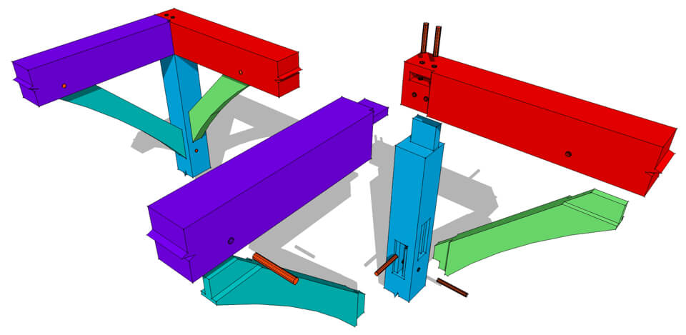
Just looking at this image, I see three distinct types of connections, circled in white below. All others on this structure appear to be one of these three, oriented in different ways?
Also think about what output you need from this project. If your goal is to manufacture on a 6-axis robot then what input does this need for programming? Is it programmed from solids or planes, lines and arcs?
Perhaps you can generate planes, lines and arcs at points along each strut that give you all the info you need to program the robot?


 awesome stuff Joseph! Thanks so much. Your script is giving me hope that it’s not an impossible mission. The planar split you’re doing seems to be a good way to go about trimming excess.