Array of compound angles creates difficult relative orientation problem

I am trying to generate a wooden form made from a chain of compound joints which use repeatable angles (requiring only 30 or 60 degree miter/bevels), so that they are easier to cut on a tablesaw.
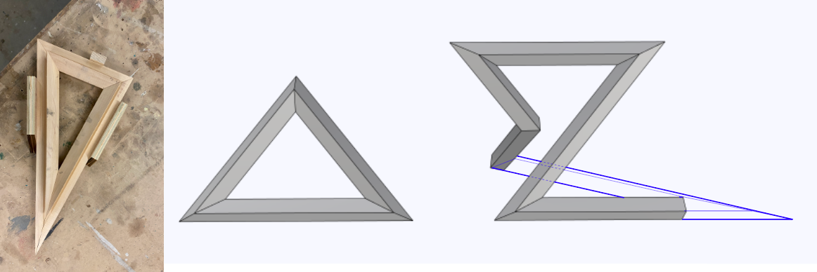
Example:

I started by manually modeling the joints with this set of angles, and extracted their edge lines as “options” to choose from for generating a polyline in grasshopper. (I would like to do this mathematically later, but this was faster for now.) I positioned each of these reference curves starting at (0,0,0) and measured their rotation angles (XY and Z) from their endpoints relative to the origin, using ToPolar.

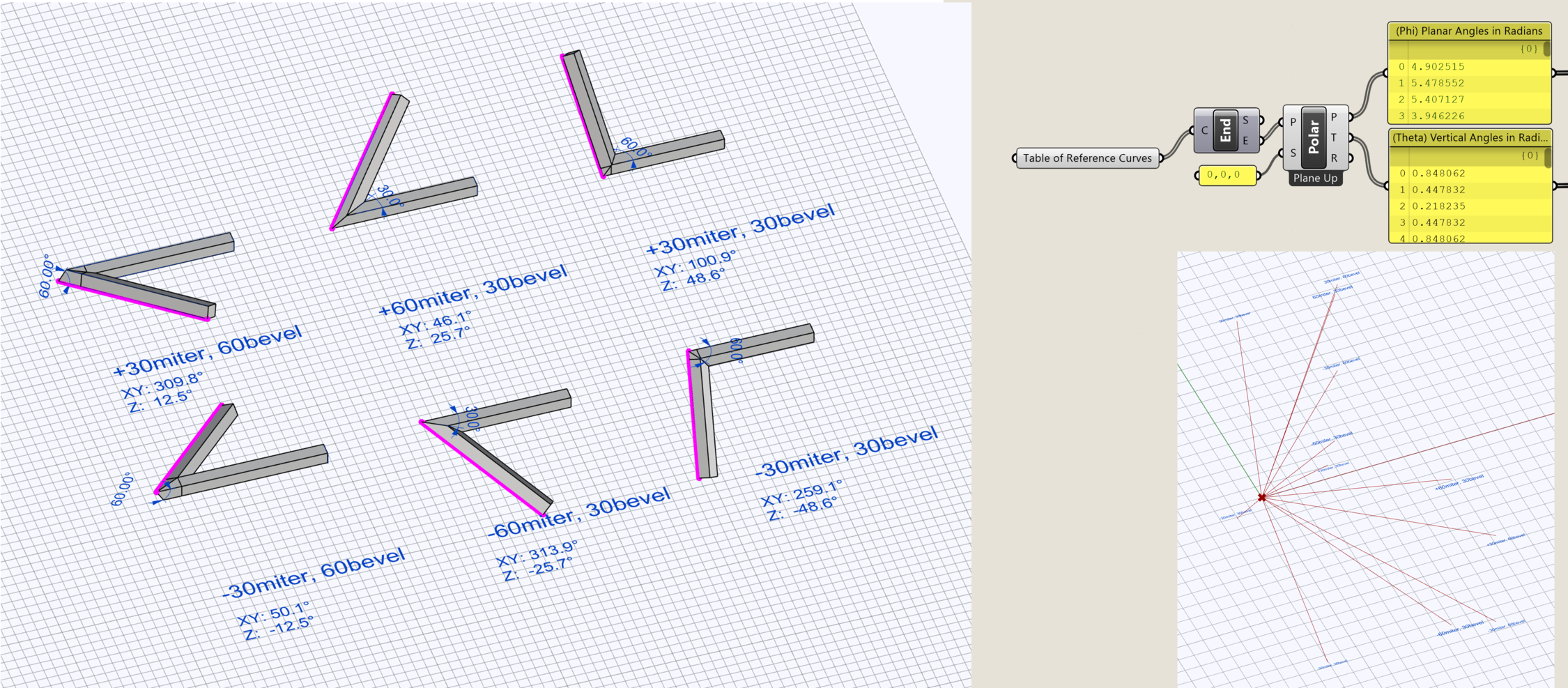
Each joint selects an angle set from these lists to generate a point, relative to a given base plane for defining the polar coordinate space, and then draws a line segment. Then I use the curve frame component at that line’s endpoint as the XY plane for defining the “new” polar coordinate system, to generate the next point using another angle set. So on and so forth. Finally I use sweep1 on the full polyline to generate the sculpture form.

My issue is that the first joint always has the correct angle after I do Sweep1 (as shown, its measurement is 30 degrees) but the second joint does not come out with the correct angle, or any joints thereafter. I manually modeled the correct version next to it, seen below.
I am not sure what is causing this, but maybe it is an issue that each segment is not properly oriented relative to the previous segment. What can I do to align these segments properly? Is there a better approach?
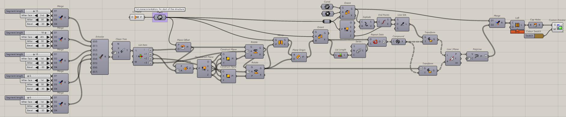

GH Script:
PolarTangle.gh (116.1 KB)

2 Likes

Hi!
Welcome to this forum!

This seems interesting! But I’m not following the logic properly…

ok, but …
Can you attach some more cases ?

The first segment:


have the cut plane that is 30° rotated from the longitudinal axis of the beam, but ALSO 30° rotated from the vertical Z axis.

Are this 2 angles always equal for you?
Or can one be 30 and the other 60, and vice-versa?

Edit: nevermind, I didn’t properly look at other pictures…

This can probably be solved very efficiently by using compound transformations and a sequence of projections or such…

…yep… but explaining what is going on is harder, though…

Anyway, try this:


PolarTangle.gh (28.2 KB)


spooky
Spooky! :joy:

6 Likes

Thank you so much, Riccardo! This seems to work correctly. I am still going through the script and trying to understand it, so I may have some questions along the way.

Two questions : I got a little confused by the operations of the planes - could you explain why you are mirroring the rotated planes across the YZ plane and repositioning them here?

Also, (sorry if it’s a lot to explain) - what is the function the “repeat” component before compounding the transformations?

Thanks again! I love the spooky feature.

You will assemble this but placing congruent faces together. Each cut in a piece will need a identical and symmetric cut in another piece.
That’s why the mirror part.
You define the cutting plane of each piece with a length + miter angle + bevel angle… but this also already define you the symmetric cut for the next piece.
So I orient following that mirror transformation and i’m ready to work on the next cut.

In reality, each cut is made relative always to the starting plane and its output are a resulting cut plane and a mirrored plane to define the orientation for its next element/piece.

This results in a list of planes (the cutting plane) and a list of transformations.

Repeat to 0> null transformation
The first element is already on the correct place

Repeat to 1> the first transformation
The second element is transformed with the transformation of the first

Repeat to 2> 1st + 2nd transformation
3rd element transformed by the compound of 1st and 2nd transformations

Repeat to 3> 1st + 2nd +3rd transformation
4th element transformed by the compound of 1st + 2nd +3rd transformations

etc

the last transformation is never used.

This is the fastest method, i guess. Using transformations and having the only iterative step being the the creation of compound transformations (light task). Every other part of the code is creating the elements in parallel (not the final loft though…).

(Probably not a good explanation… sorry … it’s harder to explain than making the definition)

Also, probably a less-abstract but slower definition might have been easier to understand and easier to edit…
If i find time I might think about it.

Questions:
How do you treat the first and last element? 90 degree simple cut? like flat head?

How/where do you measure the lengths of the elements?

Hello, thanks for these answers, and sorry for the late reply.

Initially, my intention was for the structure to be an open loop and the first/last faces did not matter (flat head). The lengths were also purely aesthetic choices.

However, to your question, I am now curious how I can script closed forms as in the examples below (rough sketch):

The first is a simple triangle, but as you add more joints, this can become very complex… and I am unsure how to create the connection between the first and last element which is mathematically possible (i.e, not some twisted loft geometry.)

So, do you think it is possible to have this script find some combination of angles + lengths to create a closed form instead? I expect some angles will no longer be 60/30 as in the previous.

But not any closed polyline is “mathematically possible”.
Imagine a helix-like polyline, that creates a lot of twisting! To connect each extremities to form a closed loop you’ll need first to do the same amount of turns in a opposite direction helix.
Some sort of relaxation is needed, maybe with kangaroo…

No, another script is needed. Probably more complex for the relaxation part. But exactly because the angles will be not fixed, it will be also simpler.

1 Like

Kangaroo.
I’ve made a custom goal that creates forces that aim to make two closed polylines be an un-twisted offset of each-other. (actual parallelism and distance forces for this are made with vanilla kangaroo goal objects).
It moves vertices to the mirror plane that divide each segment to the next/previous one.
Closed not twisted polyline.gh (23.6 KB)


2022-06-28 11_42_54-Window

If you let it converge, it will give you a polyline that can loop.
You might want to add some anchor points to help you define the shape (but you can’t anchor everything, use grab with cursor and let it converge).

Torsion of a closed polyline is enough abstract, i’m not sure this approach is good.
This method forces the shape into having 0 twist turns overall.
But, back to the helix i mentioned, you could indeed use a shape that have an integer amount of turns… it make sense.
Or even a fraction of integer turns, like if your section is a pentagon, it could have some n*1/5 twist turns from start to end and you still would be able to close the loop with faces aligned.

Another method might be to measure the total torsion of the polyline (from start to end) and apply a counter-torsion all-along inside the polyline, aiming to round the torsion to an integer or a fraction…

wtf are we doing here? :rofl:

1 Like

So, simulation means letting points move/relax, meaning you have little control on your design.

Let’s go back to a more manual workflow.


Perp Frames already solve the twist of a 3d curve.


We can see how the planes are already aligned segment to next segment for your cutting, no twist between the segments… but not for the end point!


Note how the first and last segment are no longer compatible because of the twist.
per frames zero twist.gh (11.4 KB)


So, you can manually move the points until you see the alignment is correct.
Or better, use a small c# i’ve made recently that helps you move a slider to find the perfect place:


Closed not twisted polyline 3.gh (32.3 KB)


With a 2-turns helix I’ve managed to make a twist of exactly 1/4 turn, and this is acceptable for a square profile section:

3 Likes

Riccardo this is amazing work, thank you for digging into this! Some context - this is for a project of mine, the OP (@Shray_Tripathi) is working with me on this new variation. You can see an earlier finished piece here.

To clarify: Because my goal is to have this be simple(r) to fabricate, we want a closed loop with a fixed set of miter/bevel angles (as in the OP and your earlier script with 30°s and 60°s), so we can make re-usable jigs to cut on a tablesaw.

The finished form will be a “tangled” light sculpture with continuous concealed LED strips on each side (again, here is an earlier wall-mounted version, that one used 3D printed joints to avoid this whole issue, but that turned out to be a big hassle for other reasons.

A limited set of compound angles allows repeatable cutting setup – maybe the relaxation method cannot work for this purpose?

To give you a rough idea, as in the form below, the joints will mostly form more acute angles, to create a tangled loop rather than spiral. In this screenshot you can see the final joint is not resolved, which we’re hoping a variant of your GH method can resolve.

1 Like

Cool!
I’m not understanding what I’m seeing… is the wood transparent? :rofl:
Edit: oh, is the beam section shaped like an “H” and you put the lights and then close the sides with a transparent fake wood?

eh… that picking the most complex part of the first method and the most complex part of the other methods…
If I can say something out of nothing, instinctively… if you want to re-use the same angles over and over, and IF that’s possible, I guess the final angles will be something you can’t directly control. Like they might become 29.3° and 62.8° (random numbers).
I’m totally guessing out of thin air…


Unrelated to the twisting and the close loop matter (which I have no idea on how to proceed with the new limits, for now…):
You put your square-ish beam “flat” (with one side lying on the tablesaw) and then use the miter/bevel cut… or you can twist the beam before the cut? (rotating the beam around its long axis)
This would give you more freedom.

@maje90 exactly, the form gives the illusion of solid wood, but is in fact hollow with an acrylic diffusion layer and a microthin veneer on top.

Re: cutting on the table saw - yes we are using the blade angle for bevel cut and a sliding miter angle jig flat on the table. Some flip-flopping is necessary to achieve all angles even in our reduced set (e.g. you can’t safely turn the piece on its end sticking way up in the air). There are some clamping issues as well (keeping things out of the way of the blade and fence) but in general, it works.

I’m still digging through your recent solution, but wouldn’t restricting the form to a set of exact angles be possible, as long as you’re willing to have the length of each beam auto-adjusted to fit? It’s not trivial that’s for sure, as every change has cascading effects on the chain…

But even if the angles are not exactly 30.0 and 60.0 that’s okay as long as they are the same. So we can cut everything with a set of re-usable jigs.

Ok, that was unexpectedly simpler than what I were thinking…

1 Like

Thanks, Riccardo! Looks promising - would you be able to upload your script as well?

So… a pretty limited solution.
Or better, a constrained solution.

Maybe there are other solutions… this i what I managed:
The final concept I understood, given the manufacturing limits, is:
“if you turn left, then you must turn right to get back”
(for this reason you need an even amount of segments)
… but the sequence must go forth and back in the opposite order, like:
+x +y -y -x
or
+x -y +x -x +y -x
or even
+x +y -y -x +z -z
but not
+x +y -y +z -x -z
and not
+x +y -x -y
(no idea how to better describe this)

If you use a miter of +25 degree, then you must use also a miter of -25 degree.
So, with 2 angles of miter and 2 of bevel, you’ll end up with a total of 16 combinations. (0 to 15 index)
And by how cross product component works, each bevel+miter combination index have its “opposite” at mirrored place: 0<>15 , 1<>14 , 3<>12 , etc
0,1,14,15 ok (but probably a square or a X shape, auto intersecting)
0,14,6,9,1,15 ok
2,0,5,10,15,13 ok
0,6,15,9 not ok

Also, you need directions that lets you go back, if all the segments never, say, decrease in Z, it’s not able to close the loop.


PolarTangle is back.gh (37.6 KB)


Personally I think that having limited cut angles is strange and … cheap.
If you aim to make a premium product, with unique arrangements, making a everytime-different cut (with unique bevel and miter angles) should totally NOT be a limit.
I would use [Closed not twisted polyline 3.gh] for more freedom and also exploit the 1/4 turn twist if needed (your beam shape is square-ish anyway… and why not making hexagonal beams? 1/6 or even 2/6 turn twist to even continue the light stripe…)

Forcing it to re-use the same cut angles… feels cheap, and the result are constrained, probably not possible to have a really free design…


This solution sort of works, but still a mess, like trying to make a puppy stay still for a photo…
Good luck!

1 Like

Hi Riccardo, thanks for this explanation. I see the script produces lots of twisted possibilities - am I to simply keep randomizing the genepools until the total angle error panels = 0? Or is there a faster way to reach a correct form with this script? Perhaps I am just not understanding how to actually use it properly.

… no… re-read my previous post.
I don’t really know how to better explain it.

Also… I must repeat: this is not a really good solution, with that many limits, solutions are not free and likely ugly (or you are lucky if you manage to get a good one).
Better solution … no … best solution is to use my other old script and use free miter/bevel angles.
imo

Point taken. We were exploring the optimal workflow of combinations of traditional vs digital fabrication. In my original piece, all joints were unique compound angles, but I ended up 3D printing just those components, so it didn’t matter. The 3D printed joints all assembled with identical angles to the wooden beams, which made our workflow nicer.

For this next version, we can indeed go back to unique angles for all joints, but I want all wood. So I will come up with a CNC workflow to suit. (Or maybe a precise tablesaw workflow.) And I agree it will look better.

So next we just need to make sure the LED channel meets up with itself. I.e. the twist correction analyzes for one continuous face of the profile.

1 Like

Then, this Array of compound angles creates difficult relative orientation problem - #9 by maje90
is the best workflow I can guess.
Draw a polyline, move to form a suitable design while monitoring the total twist, at the end find a vertex that, if moved, will fix the twist.