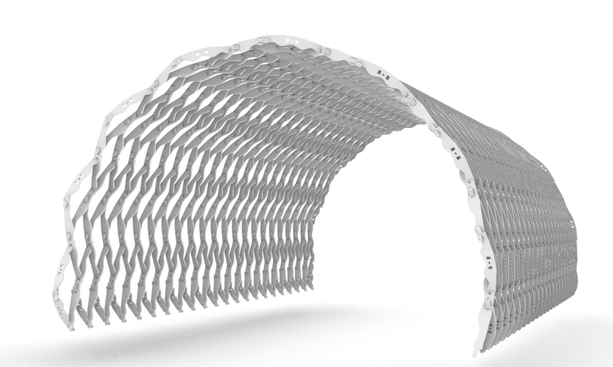
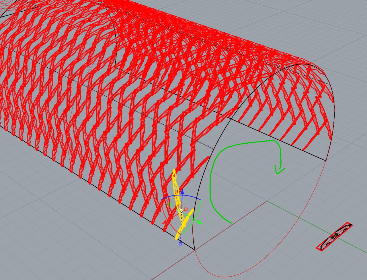
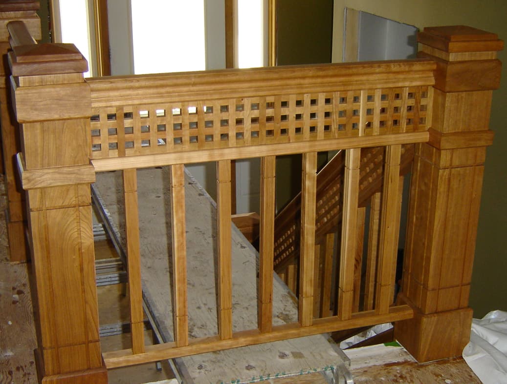
I’ve been working on this reciprocal structure script which will eventually be CNC milled. I’ve managed to get to a point where I’ve aesthetically achieved what I intended, however, it is not where it needs to be in terms of precision. The connections are sloppy are do not perfectly line up.
The structure is based on a 2D pattern mapped onto a barrel vault, which I used to create bounding boxes, to then map my modular piece into. The bounding boxes guided me in a general sense of how to map out the intersections and connections. However, has led to me slightly modifying the modular, little by little, with the intent of getting more and more precise. This has been tedious and would take far too long to actually get the precision I am looking for.
I was hoping to get some advice on modifying the grasshopper script to actually map out the intersections and creating the modular itself. This would ensure precision when putting these pieces together. I’ve attached the Rhino & GH files here. Any advice would be appreciated!
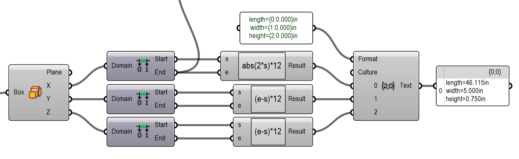
The dimensions you have are relatively correct. We were aiming for 47" as this would minimize the waste on a sheet of plywood. When the 2D pattern mapped onto the barrel vault the linework shrunk a little. Ideally the individual members would be 47" x 5" x 3/4". Sacrificing an inch wouldn’t hurt, so either solution could work.
This doesn’t appear to be necessary? The code appears to work without it.
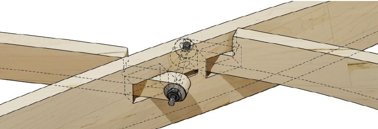
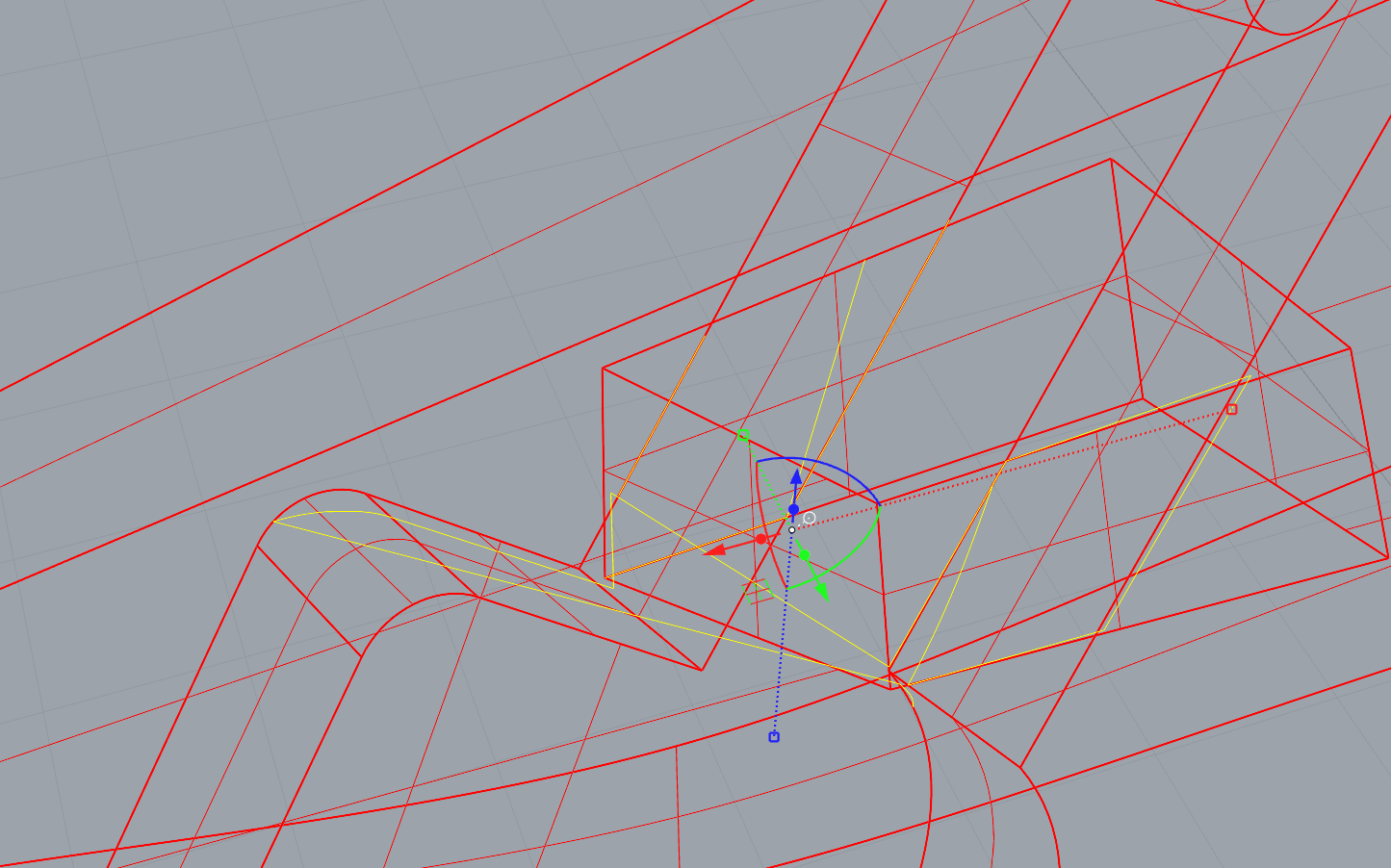
The joint looks more complicated than needed? What if you have one hole instead of three, with two ends overlapping without space between them? I guess you need to attach somehow to the piece that has the hole… Thinking out loud.
Interesting. I assumed you might be using a smaller machine hence part of the problem with your test. My 4’x8’ 3 axis CNC is on the smaller side and I can only maintain about 0.015" accuracy with some cuts. An industrial machine like CR Onsrud should be able to maintain 0.003". Accuracy will be of paramount importance here. Each error is compounded with each joint and you have a lot of joints. I have made some complicated things on my machine and learned the hard way about this.
Plywood will make this challenging given you need to use a number of sheets. Plywood is warped, and its thickness varies by 0.03" or more. I am not sure where you are in the world. You may be using veneer core plywoods, and those can maintain better tolerances. I am in Canada and our domestic sheets are better, but I would be very hesistant to attempt this with any of them. Our import plywoods are crap and would never work for this.
Baltic birch would be a little better for two reasons. The first is the edges. Baltic birch will not have nearly as many voids around the perimeter after cutting. Its thickness is less variable as well. It is sanded after pressing, so its thickness is still variable.
Have you tested the fit using MDF or melamine? Those are both much flatter and the thickness will only vary by 0.005". These are both very cheap (where I am) and I would test your current parts for fit.
I will ponder the joints to see if I have any other ideas to toss out amoungst all the others. It will be a fun project, so I will help if I can.
@Jake_Blasko
A few notes, as I have done quite many of these, but with varying parts.
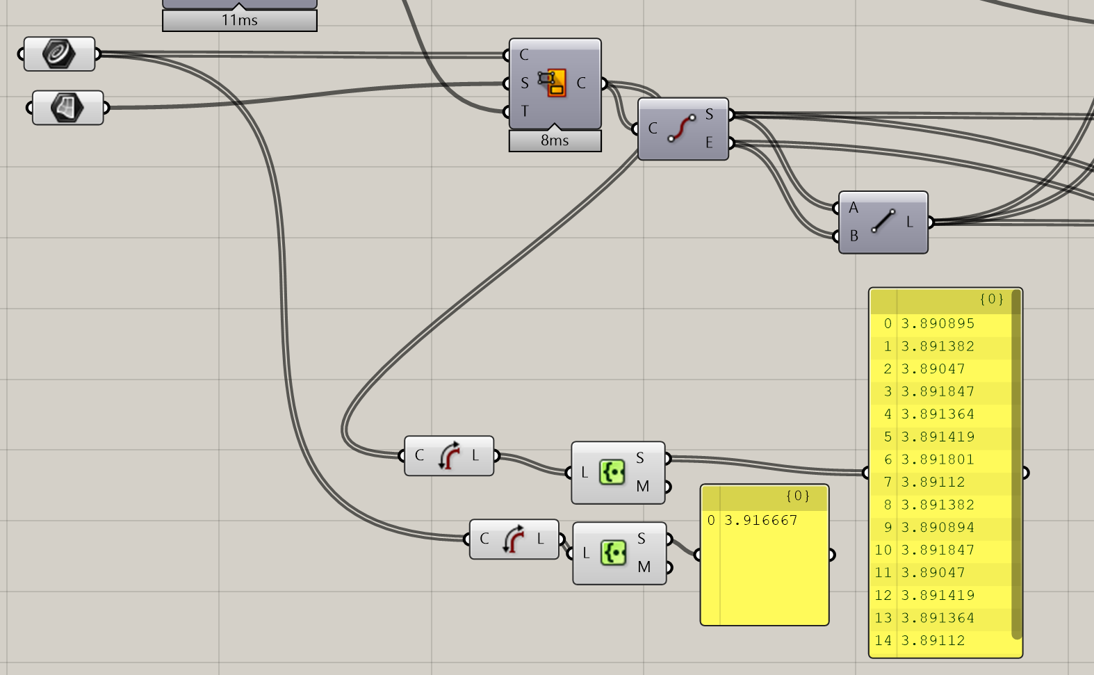
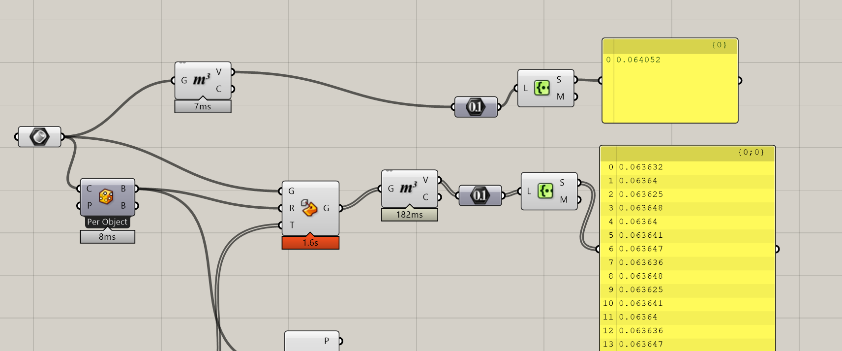
First off, you are introducing inaccuracies in to the system with at least two no-no components, regarding digital fabrication.
The lengths of the grid lines are uniform prior map to surface, but not after.
I don’t know what these are in imperial, but from 3.91 to 3.89 is a substantial difference.
The second component you should never use in fabrication is Box Morph. Here, it is not that dangerous, as you are morphing from box to box, but you are once again introducing possible inaccuracy point to the system. The box morph should be replaced by orient, IMO. But here, luckily it does not play such a big part. There is slight volume difference here.
Given that the part you wish to fabricate is the same on all locations, I suggest that use a block as the starting piece. There is minimal risk in accidantally modifying the geometry.
There is a large collision between the parts that could be fixed by widening the gap. I ran _intersect on two parts here.
Not sure why lunchbox is showing up when no components from lunchbox were used..
I liked the idea of the through-bolt, rather than a lap joint of some sort, as it would enable us to apply more tension to the joints as needed, and to evaluate how the structure would react.
Very open to thinking out loud, thanks for your input!
I do not think the issue lies in the machine but rather the sloppiness of the 3D model itself. I was never able to attain a perfect joint in rhino but wanted to try to test cut some pieces just to get a more tactile feel of the pieces. We are indeed using 13 ply baltic birch, which seems to be pretty consistent, but will definitely try out mdf in the future for the test pieces. Hopefully I can find a better means of form finding when it comes to the modular piece. Thanks for your reply.
This seems fun, so I am going to create my own model to see what I think of. I may test cut some pieces as well. I see the others found some small errors in the model. I had not looked at that yet.
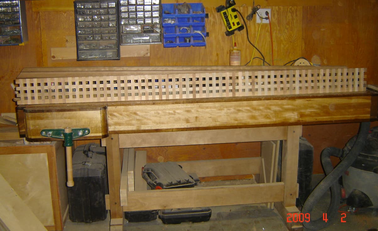
You will need to test a number of parts to figure out the best tolerance settings. I recall making the half lap lattice you see below. That had to fit into mortise joints and I did not want ugly gaps. I think some pices had 100 or more cuts. I found thousandths mattered since the errors were cumalitive. I was doing this on a sliding table saw at that time, but the problem will be the same for you.
Thanks for all your input, I have a couple questions in regard to your feedback.
I understand the MapToSurface component is causing some warping, do you know of any comparable components to use that would enable this same effect without the warping?
If I was to start this process with a block, like you recommend, that would change the entire script correct? Could I still somehow map that block onto the 2D pattern? Or should I approach it by trying to parametrically generate the pattern in 3D space using grasshopper? (which was how I began this process but couldn’t figure it out and created this workaround solution)
Also, in regard to intersections, do you know of a way for grasshopper to generate the form to make seamless connection minimizing collisions?
Sorry this is a lot and I am relatively new to grasshopper. Thanks for your help!
I think for my case, I want to exist in-between the two extremes: tight tolerances will enable a more rigid form, however, for the sake of quick and simple assembly we want a little bit of play, and the through-bolt will enable us to tighten those joints as needed.
I understand what you’re getting at, one error will get compounded and when you have 400 members that error will only become more and more exacerbated.
That lattice is awesome, that’s a whole new level of precision!
Have you accurately measured the actual material thickness with a micrometer, dial caliber or similar? How does the actual material thickness (not nominal or claimed by supplier thickness) compare to the thickness used in your model?
The actual material is about .704" whereas the 3D model is .750"
Yes, this is something I should have considered before hand but in theory I was testing the tolerances in the other directions and the thickness shouldn’t have that much of an effect. but worth changing while moving forward to make it more accurate.
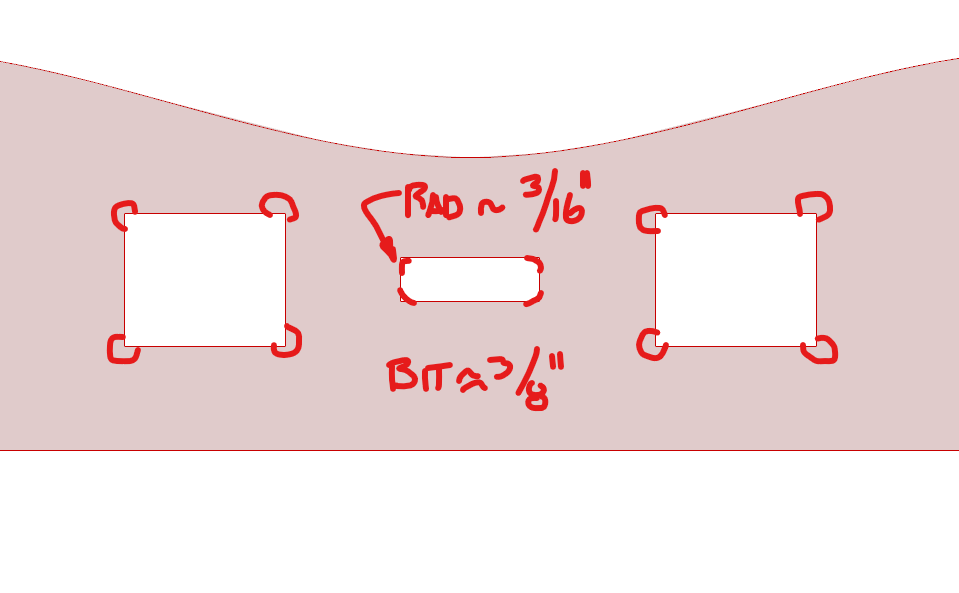
I would add the rads and dog bones into your model as well. I like my models to be as exact as possible so you can check things that might not be immediately obvious. I would expect at least a 3/8" diameter bit will be used. Maybe larger if cut speed important.
I am not sold on a few aspects of the model yet, but I will not have time until later to test my ideas.