Parametric Japanese Timber Joinery for post and beam construction

It’s programmed from solids. The general process would be:

  1. Create solid geometry in Rhino.
  2. Use CAM software (maybe powermill?, but it’s very expensive) to generate machining paths
  3. Use machining paths with RoboDK to control actual robot

Possibly, later on, have an aditional step with the robot and doing automated photogrammetry of the work piece, but yeah that’s a year or two away…

Thanks for the the links. I’ve seen the GIFs before, but not the TimberframeHQ site. :+1:

You are correct, but there are an almost infinite amount of joints possible, best to just to attempt to deal with members meeting at 90deg to start with and go from there.

Here’s a version with internalised geometry.
2019 Parametric Joinery Dev01.gh (13.7 KB)

Hi,

Can you give a reference of the paper that you posted the picture from?

Have you looked at Fusion360?

Here you go.

Yes I have looked at fusion360. It doesn’t really do what grasshopper does with regards to scripting.

It does 5-axis milling paths, but I haven’t really tested that feature out. I do like it tho. It has a great UI

I wonder in anyone is working in something like RiF, similar to RiR (Revit - McNeel Forum) so you can have Grasshopper-driven geometry inside Fusion and then do your toolpath work from within Fusion.

I don’t see any 5-axis toolpaths here, though.

It’s indexed 3 axis or indexed 4 axis.

I don’t see many examples where you’d need to be moving through all five axes simultaneously.

Fig. 6 can be done on any machine with a C-axis aggregate.

This cobbles together some bits used previously to explore the scarf joint. Rather simple until you get into its variants.

Scarf Joint With A Wedge has two wrinkles: 1) the scarf surfaces interlock, requiring two levels on each block and 2) the wedge (or pair of wedges).

The best example I found was this one: Undersquinted wedged scarf joint

Complicated! So I looked at an easier one: Post or Rafter Scarf Joint


joinery_2019Oct13b.gh (45.4 KB)

P.S. More variants of the scarf joint - precise and invisible, fine craftsmanship!


And with hidden pegs:

2 Likes

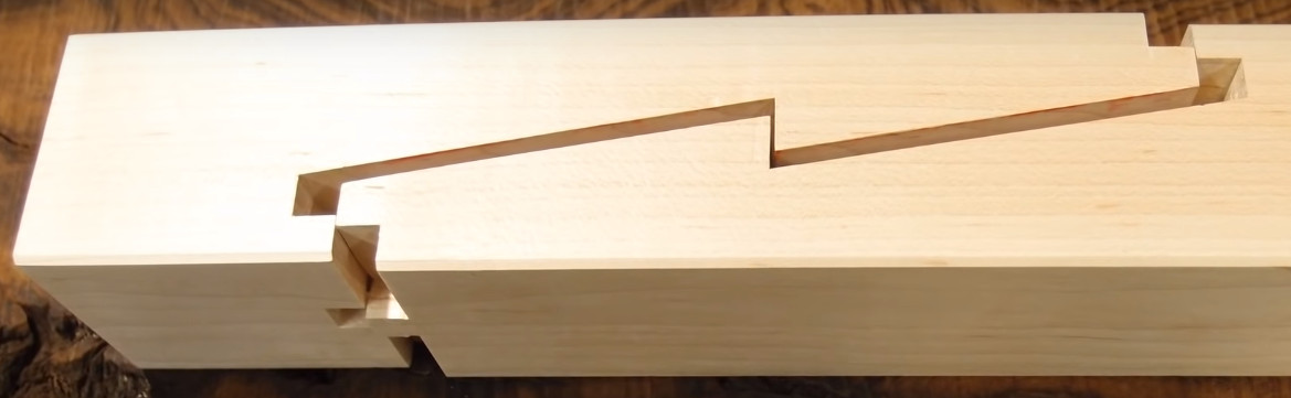
Just a heads up: the angle in the middle is too acute to be cut with a CNC router unless you either do a finish pass with a V-bit, set at an angle or you fillet the inside corner.

Are we talking about a 6 axis robot with a tool changer on it?

That is the end goal. No tool changer yet, a bit out of my price range.

An interesting plugin for timber joints is out from food4rhino and looks very promising. I tested the sample files, it gives a lot of ideas!
https://www.food4rhino.com/app/reindeer

2 Likes

Japanese Timber Joints

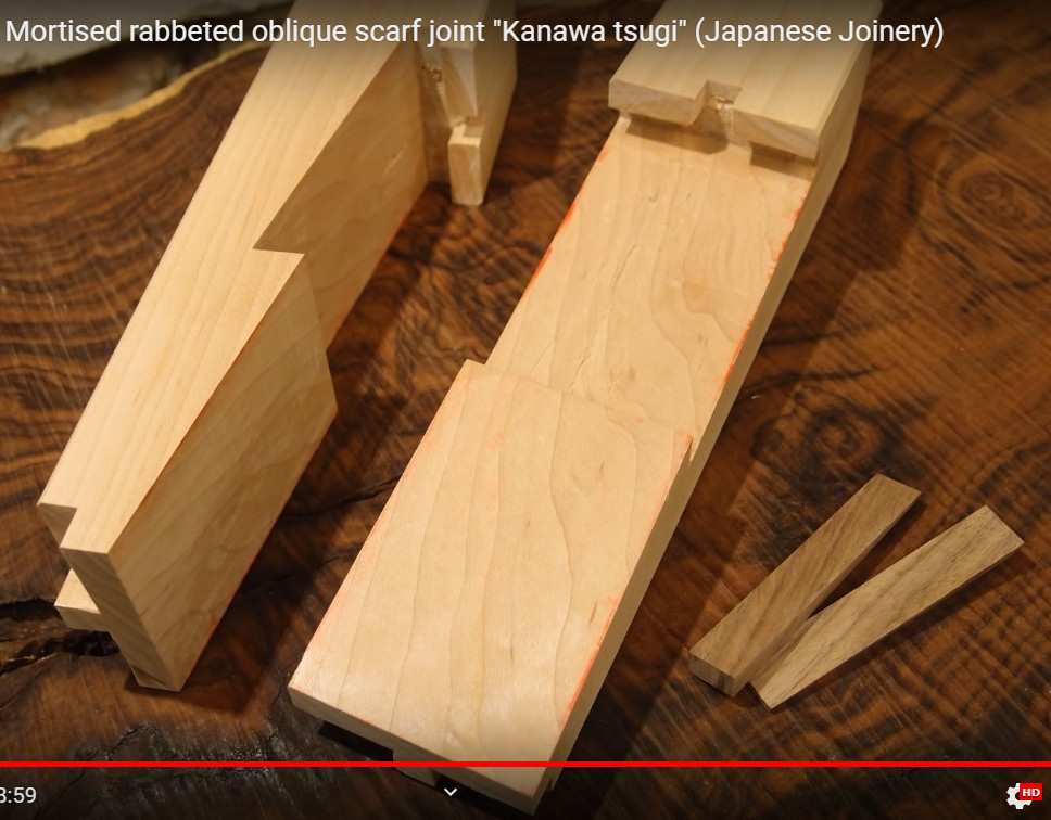
I saw this yesterday and it’s quite relevant to some of the discussions that have cropped up on this forum.

I haven’t tried the software yet but it’s free apparently.

I would need to convert my CNC to be able to hold beams vertically to machine the ends to make use of this software but it looks like they have thought of everything in terms of angles, number of members meeting at nodes, router cutter radius, friction surfaces etc etc etc.

Check it out and if you remember any of the other timber joint discussions on here perhaps share the link on those too.

TSUGITE

1 Like

Thanks for the info Martyn. Finally getting my robot up and running again. Good to see some new research being done. :slight_smile:

1 Like

This could be particularly good if you have a robot as you could machine the ends and faces on the same setup by holding the timber flat and in the centre with access to each end so machining sets the length of the timber too.

I couldn’t get the software set up but it looks like everything is provided to do so if you know what you are doing (I don’t :slight_smile: )