Context:
I have 02 3D curves that are the bottom reference of the road.
I want to define a flat slab below the road. The slab must to put right angle to keep the thickness of variable part as small as possible and the max distance as minimum as possible.
What I did:
I’m trying to find the plane that the total distances from the curve to the plane as small as possible. (the plane can not cut the curves).
I used Galapagos to optimize the total distance. (see the GH file). Findplane.gh (25.9 KB)
The issue:
Each time I run, I find a new plane that is not fit with the old plane. (sometime it can not finish the test. )
Your geometry is extremely far away from the origin which makes it painfully slow for Rhino to manipulate (gumball rotation) and can cause errors. GH is extremely unresponsive.
Your unit dimensions are mysterious. Your curves are ~55 thousand units long!? The end points of your curves are ~1400 units apart (millimeters?), and one end is ~1000 units wider than the other?
Your curves are going opposite directions. And they are polylines so lofting them together makes a polysurface instead of a single surface.
Findplane.3dm (279.5 KB)
Here is the result from Galapagos that I was looking for- One plane - it will become top of prefab beam for the next step. The polysurface is not accepted.
Look, there was an error in version ‘b’ above, due to the difference in scale of the two models.
Fixed below. The Plane Fit ‘dx’ (deviation) is only 15.58 units (millimeters?). You can move the plane that far down if you must. The fact is though that your curves are not co-planar.
The surface need to be under of the road. So I moved it down -205mm.
I tried move up 15mm, but the total length is not optimize compare to the galapagos.
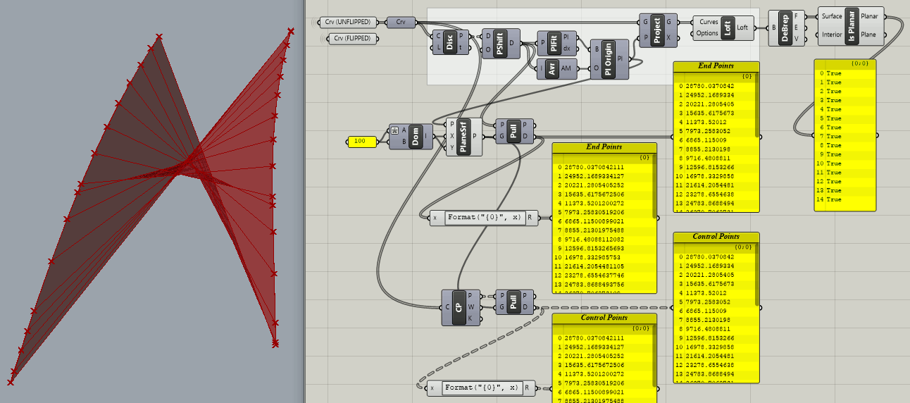
Using all the curve control points instead of only the end points (see switch in blue group below) , the Plane Fit ‘dx’ (Deviation) jumps from 15.58 units (millimeters?) to 100.27 units!
I have no way to determine which is the “better” Plane Fit result? Regardless, note that I projected the control points to the plane and created co-planar interpolated curves (IntCrv) before lofting to make the planar surface.
P.S. Using curve division points (10 per curve) for Plane Fit instead of end points or control points, the deviation is 86.0 units.
In retrospect, I realized that projecting control points and interpolating them wasn’t a good idea, so I looked at this again.
First, I had to deal with the extreme unresponsiveness of GH/Rhino, which made it too difficult to modify the model. I added a switch between “In Place” and “Move to XY”, which moves both curves to the ‘World XY’ origin. This fixes the poor responsiveness issue!
Later, I discovered accidentally that this revised model works well “In Place” as long as certain kinds of geometry are avoided. For example, there is a disabled “SLAB” group with a big warning to “Use ‘Move to XY’ feature before enabling”.
Otherwise, I added some features and options to visualize the true shape of your curves relative to a ‘World XY’ plane with its origin at the lowest end point (white ‘X’).
‘Plane Fit’ origin is adjusted automatically to the lowest position to avoid being above any of the points. The blueish surface below uses the original curves and is definitely not planar! The light green surface is planar, derived from projecting your curves to the adjusted ‘Plane Fit’. But is that really what you want? It appears to deviate from the original surface by up to ~220 units (millimeters? 8 inches?).