I am new to grasshopper and I have watched some videos to try to get some of the basics. I want to make something that looks like an umbrella where I can use the slider to choose how many posts the umbrella has and between the posts a little sag occurs. I would imagine this is easy, but I cant find a video that deals with something similar. Can anyone point me in the right direction? Thank you for the help.
-Daniel
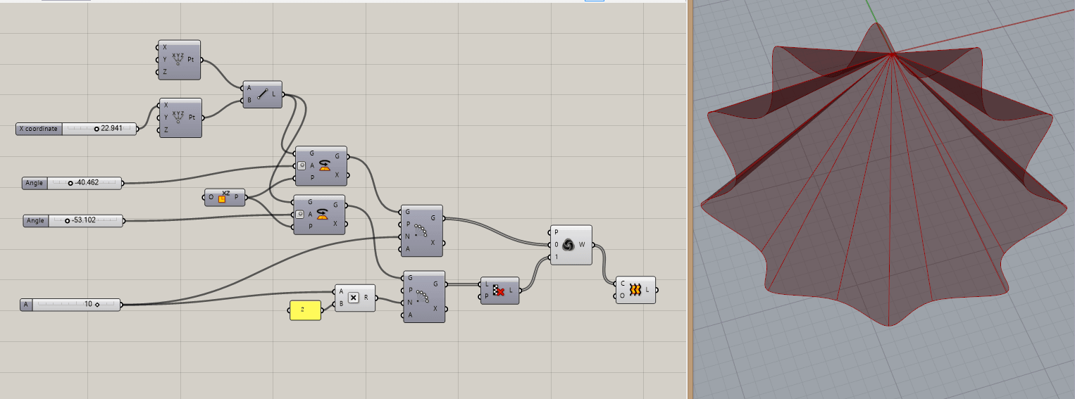
Cool idea… only took a few minutes to hook up… Here’s how I’d go about it.
Umbrella_BrianJ.gh (11.8 KB)
1 Like
Awesome that will give me some ideas to go off of. I will just need to figure out how to use a curve I have already drawn in rhino instead of creating a line. Or I could try to create the curve in GH I guess. The final design is going to be like a glass shade looking thing so this is a great start. Thank you Brian.
Hi there.
If you have a curve already drawn in Rhino, create a “curve” component in Grasshopper. Right click on it, “set one curve” and then click on the curve in Rhino.
Do it as Tabak described in that case. If you align the curve along the same axis as I have, the rotation components should work as expected.
Brian, I used your template and got this far. I am having a problem though if I change the start Z from anything but Zero my loft gives me an error, do you know why?
question.gh (10.1 KB)
Hi there.
Had also a quick look at this too. I have plugged the points to the polar array P inputs and the second point to your xyz sliders. With this everything follows when you change the xyz values. But the loft still won’t work with different values other than 0 for z and y… But you could always move around the whole loft to another location afterwards, couldn’t you?
question_2.gh (15.2 KB)
I’m not sure exactly why that breaks the loft… the runtime error message doesn’t help either (@DavidRutten may know if this is a bug or not). I would agree on the idea of moving the final loft instead like this in the meantime.

Even though the X and Y do neat things, that is not what I was thinking they were going to do. I was looking to move the whole thing around similar to what I was doing with the Z. I think the problem is in the VRot, it rotates around the Z axis instead of the given point. Any ideas on how to change that input to follow my initial point?
I thought the same thing but was not able to replace the plane of rotation for the vectors with success, after a new look at the file I see now it’s the plane for the rotation of the spline that needs to change. Then any Z value will work…

I’d probably still place any orientation or move components at the end personally.