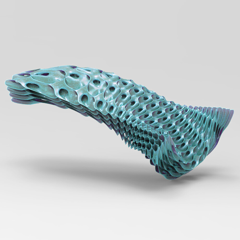
I’m trying to do something that I think is more complicated geometrically and mathematically than I fully know how to describe, but effectively what I’m trying to do is create a morph between these two reciprocal gyroids. Below is an animated GIF illustrating I am trying to accomplish, but I want to create a “stack” of these iterative voxels that change from one extreme (dominantly gray)(-1.3 iso value) to the other (dominantly green)(+1.3 iso value) while maintaining a continuous surface. Below is also an inspiration image made with Pufferfish Pufferfish that does something similar.
Here is also a link to download the Milipede plugin which normally takes some hunting if you’re attempting to open my file.
Looking forward to hopefully making some progress! Thank you
Indeed, i did not fully understand your post … but also english is not my main language.
That IsoSurface thing split space into 2 volumes. I your values are “symmetric” you will have the 2 volumes splitting space half-and-half and possibly even being conguent.
Looking at your gif, volume green and volume white, let’s call them A and B.
The Pufferfish image you attached seems to have constant 50-50 splitting between A and B in all its places, but the “lattice” is stretched by some rules.
What I feel you want is to obtain something different, a lattice where a side have A/B=0.1 volume ratio and the other side A/B=0.9 … ?
To achieve so, work with iso values.
Work with attractor points or distance based interpolations.
With “Remap Numbers”, use your attractor (which should go from 0 to 1) as value and “-1.3 to +1.3” as target domain.
Try with something simple first, use “Clipped” output.
Currently away from home so i cant help further.
Keep us updated.
Yes! You have it correct, both about the precedent image and my intentions. I’ll look more into iso value manipulation within a single output, but I’m attaching a diagram I made to clarify further if anyone else is confused.
To vary the iso value with position, one way is to take the expression for the gyroid and add another term which increases the value by some amount depending on position.
Here trying with the isosurface script I just posted here.
The key part if you want to modify it is line 163-166
Hi Daniel,
thanks very much for the graded gyroid, however, for something even more fluid in gradient, is there a way to have two surfaces (one on top and one at the bottom) to control the height and sizes of the gyroid to make it completely asymmetrical? I was trying to create a cluster or an additional script for the boxed gyroid I have successfully created, but having difficulties working it out…
Also, for more powerful tools for working with implicit surfaces, try this:
Though in this particular case where you simply want to map a regular TPMS between a pair of NURBS surfaces, I think the explicit box morphing approach I showed above is more appropriate. You can also do these sorts of morphs implicitly, but taking one mesh and morphing it to each of the cells is actually much more efficient here (resisting the urge when having a hammer to see everything as a nail!)