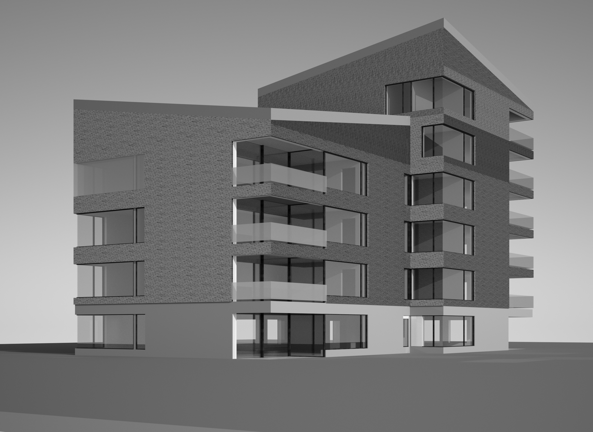
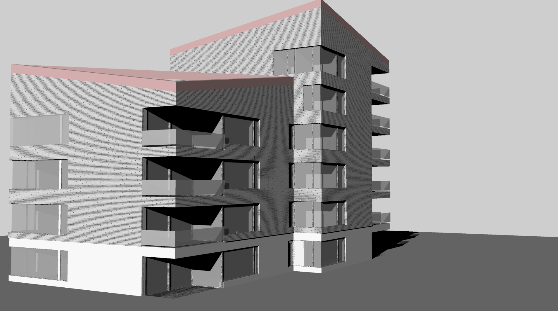
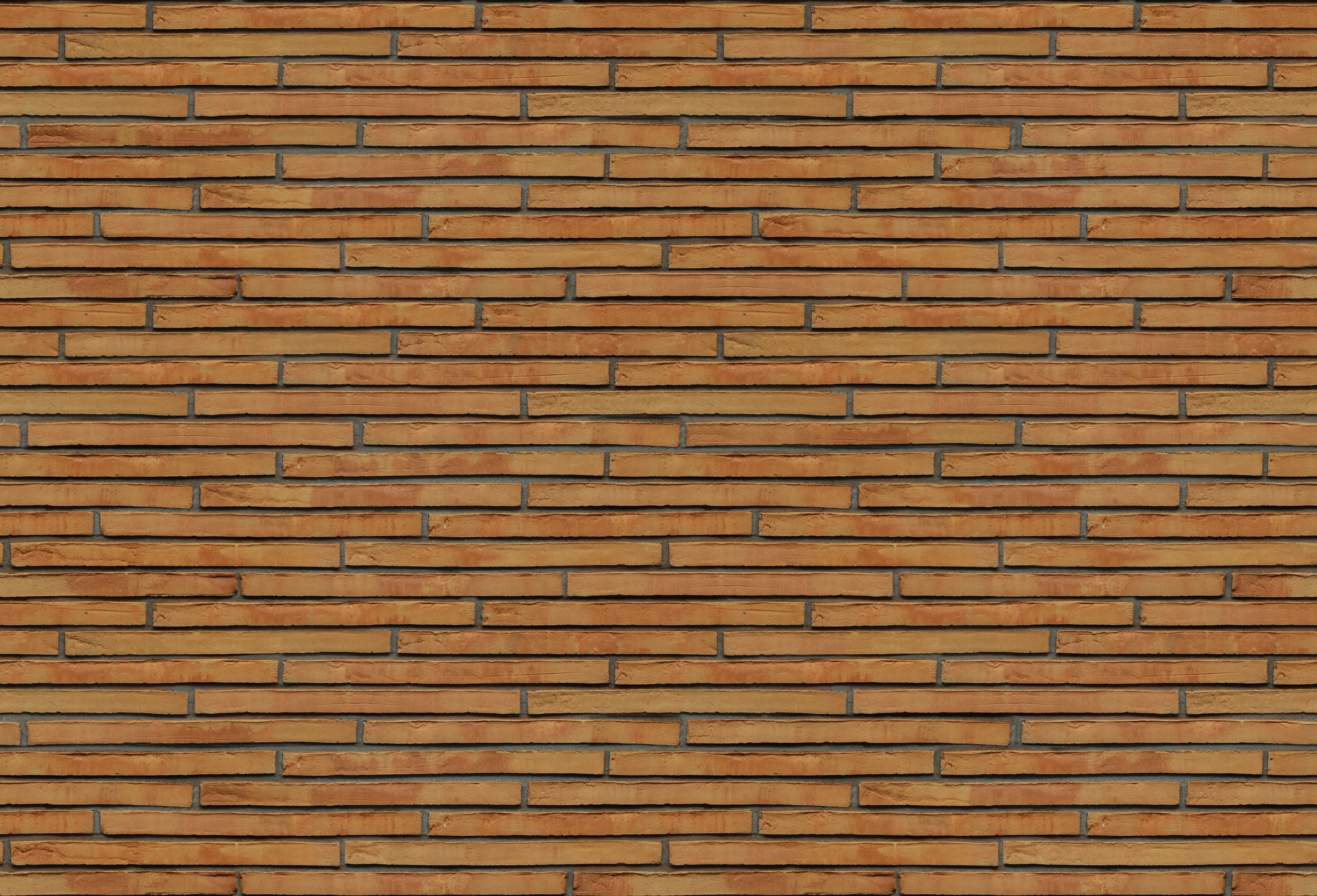
Not a stupid question, UV mapping can definitely be one of the more esoteric aspects of modeling & rendering. Since you say you don’t understand how it works, I’ll give just a bit of background. When you render (at least in Maxwell), you are always rendering a mesh, which is made of triangles (and quadrangles, which are ultimately split into triangles). In order to apply a texture to a particular triangle, it is necessary to know where on the texture image plane the triangle lies, so each vertex of the triangle is assigned U and V values, generally between 0.0 and 1.0, indicating its position on the plane (you can think of U going along the X axis and V along the Y axis of the plane).
The question is: how do these UV values come into being? A triangle exists in 3D space, and there is no sense in talking about how it lies on a 2D plane, unless we first define how that plane relates to the triangle in 3D space. We might do this by saying that, similar to the 2D image plane, the source NURBS surface also has a U/V domain, and take the UV coordinate for a triangle vertex from where it lies on the NURBS surface from which it was derived. Or, we might arbitrarily position a plane in 3D space and “project” it onto the mesh, basically finding the point for each triangle vertex which both lies on the plane, and is perpendicular to it. Similarly, we might choose to do this using a box, or a sphere, and so forth.
With this knowledge, we can see that the only mapping projections that make sense when talking about making textures appear to be a real size in 3D space are a plane or box, because if we were to project from, say, a sphere, the real size of the image as projected onto the mesh would depend on its position in space with relation to the sphere. Well, to be accurate, it would also be possible to manipulate the “size” of UV space along a NURBS surface, such that a given distance marked out along the surface would correspond to the same distance in real space. But this discussion will be about projections, so we will deal with box projections (in this discussion, there is not much reason to talk about plane projections).
The next question, then, is how the size of the projection box is determined. You can define a box mapping in Rhino’s texture mapping panel, but if you then scale the object to which it has been applied, you’ll see that the coordinates follow along with the scaling, which is not what you want here. Furthermore, not only do we want the size of the box to remain constant, but we also want it to pay attention to some other aspects of the object it is mapping; when we move or rotate the object, we want the box to maintain its relationship with the object, such that the UV coordinates we’re generating will “stick” to it, and we won’t just be moving the object through a cubic UV space defined by a static, global box.
When you apply a Maxwell material that uses at least one texture with Units=Meters, then rather than export whatever UVs might have been generated for objects to which it is applied, the plugin instead generates (or, rather, arranges to have Rhino generate) new UVs for those objects on the fly, using a 1 meter box projection (as the Units=Meters setting implies). Then, when Maxwell renders this texture, rather than squeezing N-copies of the texture into UV space according to the texture Repeat values, it instead stretches them according to the reciprocal of the given Repeat values, the result of which is that by specifying Repeat U=2.0 and Repeat V=0.5, you will see the texture projected onto your objects with a real size of 2m x 0.5m.
In order to have the projection box “stick” to the object when you move or rotate it, the plugin uses some information it finds on the object, and which it is able to use to determine a relative transformation for the object since its creation, in order to transform the projection box. Because the initial orientation of this frame of reference is arbitrary, it may be (as you saw in your original post) that textures are initially projected in an orientation other than you may want, and you will need to use the RS Rotation XYZ values in Object Properties > Maxwell to adjust it how you want, on an object-by-object basis.
If you have followed this far, you can see why it is important, when using Real Scale (the Units=Relative/Meters dropdown used to be a checkbox called Real Scale, and I still find it clearer to refer to them this way), not to put any barriers in the plugin’s way, in the form of explicit mappings set up in Rhino’s Obj Properties > Texture Mapping, because when you do, there will be a fight between Rhino and the plugin, for how the objects should look in your viewport. The rule of thumb is, when using Real Scale textures, make sure Maxwell is set as the current Renderer, do not give objects any explicit mappings, and do not use a Channel value (in Maxwell textures) other than 0.
There are a couple other considerations too; first that it may be necessary, from time to time, to use the “Refresh Viewport Materials” button found in the Scene Manager > Materials toolbar (it also appears in the plugin’s Functions toolbar), to regenerate UVs for Real Scale objects in the viewport. This will also happen automatically whenever modifying material values if the “Enable Real-time Materials” check-button, just next to “Refresh Viewport Materials” in the Materials tab, is checked. Also, there is also a Maxwell_RealScaleUpdateMode command you can use to enable a mode in which the plugin listens for changes in the scene and attempts to update RS UVs in response to objects being modified; this is not enabled by default, because it is questionable whether what it does is really allowed by the Rhino SDK; technically, UVs are object data that should be modified only in response to user input, not in response to changes made to objects in Rhino, so, this command is not even documented.
And second, I find that there is trouble, with extrusions in particular (so, unfortunately, with NURBS boxes as they are created in Rhino 5, by default), where the data the plugin uses to maintain the relative transformation of the projection box is handled differently by Rhino, preventing this part of the feature from working. You should be able to compare the behavior between two boxes, one an extrusion, and the other an extrusion that you have exploded and re-joined (or created as a regular box in the first place), and see that whenever UVs are generated for the extrusion, they are generated at the correct size, and that they follow the box when you move it, but that they are aligned with world XYZ whenever they are regenerated, instead of remaining aligned with the object, whereas with the regular box, when you move, rotate, scale 1D, and so forth, you should find that the UVs always remain “stuck” to the object, as is obviously preferable.
All said, Real Scale is a feature that can be powerful, but which can be somewhat difficult to understand and use, and I have considered removing it from the plugin several times, because I think that by rights, the generation of UVs is something that should lie not in the domain of the renderer, but of the modeler. It would be preferable, in my view, if the cubic projection in Rhino’s Texture Mapping had an option to make it work like I try to make things work here – to keep the projection box a constant real size regardless of object transformation, and yet also to have it maintain its relative transformation with respect to the object as the object is modified over time. This, combined with, as it works in Maxwell, an option in textures to communicate that they should be stretched by the reciprocal of their Repeat (i.e. Size in Rhino textures) values, would put this functionality inside Rhino, where I think it belongs, and where it would be something not avalilable on a plugin-by-plugin basis, but which could rather just work automatically with any plugin. Until something like that shows up, I suppose I’ll keep the RS code in the plugin, since as I say, confusing as it may be at times, it can nevertheless be a powerful feature for those people whose work calls for it.
I hope this helps explain things for you, and please just let me know if you have any other questions.


