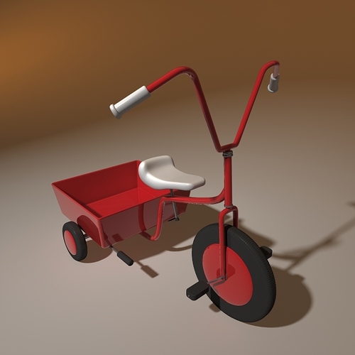
can someone teach me how to make a profile on a tire so it is just a fantasy project for learning
greetings Pet3 wheeler.3dm (1.2 MB)er
Hi Peter - an accurate tire cross-section shape, or the tread pattern?
-Pascal
Hi Pascakl nice to here something from you i think for this a pattern will do the job ? it is just learning for me
Next question: do you need to model the tread in 3d, or render a tire that looks like it has tread? If the first, I would lay out the tread pattern flat and FlowAlongSrf - one repeat of the pattern then make n ArrayPolar to get it all the way round. I’d play with a simple checker pattern or something just to get the process down, then make your ‘real’ patterns. I’m not sure if I am answering your actual question though…
-Pascal
Hi Pascal that make it a little difficult there are more ways to Rome- but lets try a 3d you point me a little in the good direction its late here i will give it e try tomorrow
greetings Peter
Hi Peter - see if this file gets you inspired. The red target surface is rebuilt (32 x 32)from a slice (Split >Isocurve) of the main tire surface. ArrayPolar, 24 x in Front to get the full half-tire , so to speak, tread.
Wheel_PGSimpleTireTread.3dm (829.5 KB)
-Pascal
de surfages you made 1 have a total different dimension as surface 2 and also a totally different shape how did you do this and how did you know the arry has to set at 24 ?? thanks in advange Peter
Hi Peter - the surfaces are flowed according to the U & V of the base (cyan) and target (red) surfaces - Since the pattern fits exactly in the base surface, it also fills the target surface and deforms accordingly. I knew I wanted 24 units because the target surface was chopped out of 1/24th of the actual tire surface (Points mark the 24 divisions, I used these to snap an isocurve to split out a piece of the tire surface, which was then rebuilt to be denser (red surface) and with more even UV parameterization.
(if you work out the length if the flat segment, which I did not, before making the pattern, the distortion will be less)
-Pascal
Hi Pascal it just magic for me that array problem i think i understand that
1 first you split up the middle or the array pad in24 pieces. and follow the procedure after that i am confused
try google translate but ???
its just the surface 1 how did you make it as part 2 ???
Hi Peter - see if this helps:
http://screencast.com/t/XV0qUmJdM
I’m not sure it gets at your exact question…
-Pascal
yes pascal i was thinking in the same direction -
but what i don,t understand is the relation between part 1 an 2 or between 3 and 4 what is happening here
how can you transform 1 into 2 or 3 into 4
i hope you understand me-
greetings Peter
Yes - use Dir (Direction) to get the two surfaces to correspond in U and V, then do the flow, picking the surfaces at corresponding corners.
Does that do it?
-Pascal
i think you understand my question this is new for me so i have to study coming day
greetings Peter-
Hi peter1,
this tutorial “Rhino V5 | Modeling an Automotive Tire” might help: https://www.youtube.com/watch?v=AfFjumHO1CE
greetings
Ed
i pascal this comment and procedure i cannot find it back in the program ??? so maybe you wil explane it a bit more
if i type in the command line dir or direction i get this

greetings Peter
many thanks Ed it good study material for the coming weeks also to use in other modelling problems
greetings Peter
The top choice : Dir. Or Analyze menu > Direction.
-Pascal
i want to say thank for the help i made a nice 3 wheeler… just for practice some basic stuff i think-
after that i start with some serious work a bike
Cool!
-Pascal


