I’d like to share my method of making this non-stretching foldable facade using GH ! (No plugin needed, but a bit C# coding is needed)
Notice: This is just a prototype, and may need some debugging afterwards.
Here we go…
Step 1.
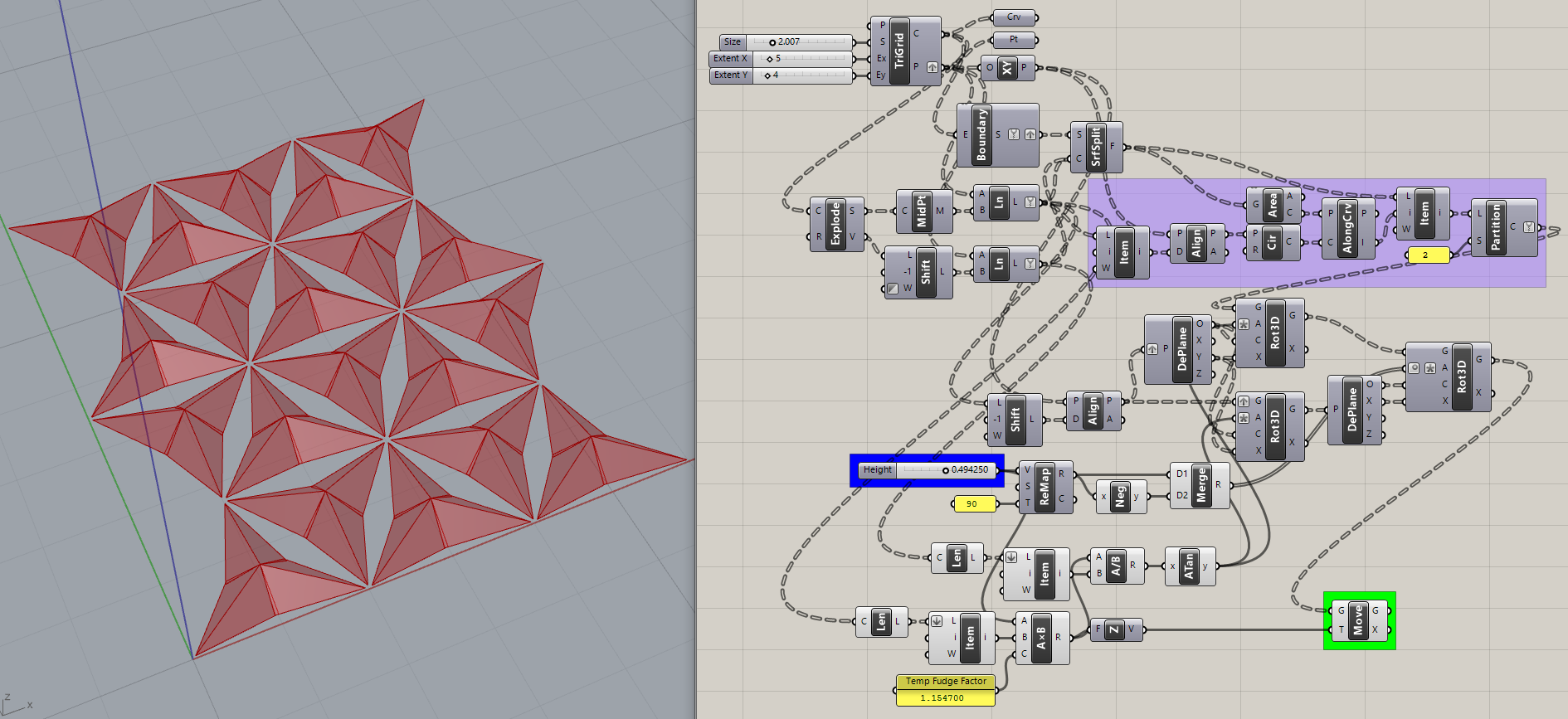
First we need to make some triangle meshes. I’d prefer equilateral triangle (or similar to it), otherwise it will look weird.
Since it’s not today’s topic so I won’t cover how to make it here. We begin with these meshes.

Step 2.
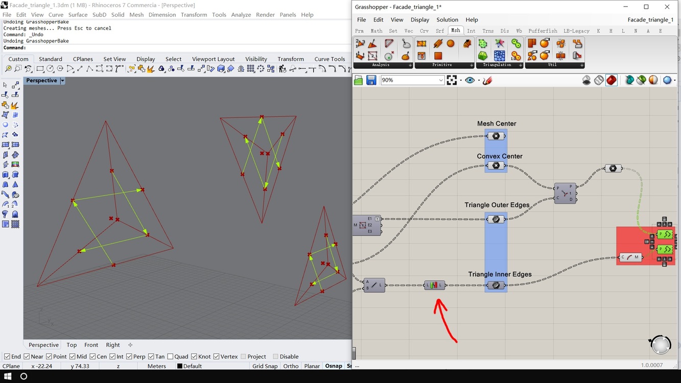
Then get each mesh center, and move them along their normal, this will be the top point of the convex shell, so we call this parameter “convex height”

Step 3.
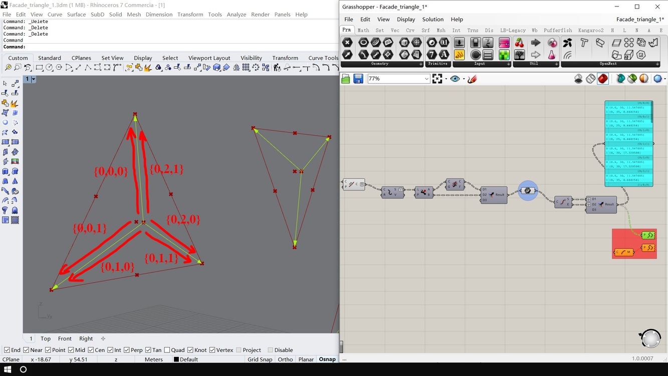
Make lines with “convex center” and triangle points in each group. We call these edges “bone edge”

Step 4.
Here I only keep few triangles for better understanding.
Project elevated center point to each triangle edge, and we got points for folding panels (We call them “folding points”). So far nothing important, just basic manipulations.

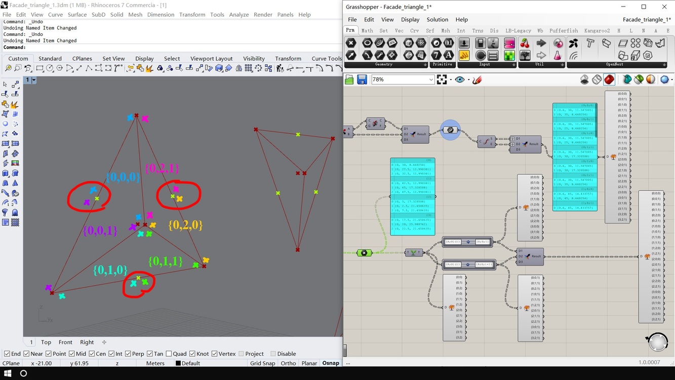
Step 5.
Here comes an important part, we have to check whether the order of each point matches the order of each bone edge, and apparently they don’t in this case, so we have to unify them.


By reversing list and shifting list, we can match each point to their corresponding edge.
Step 6.
OK, Here’s where the fun begins.
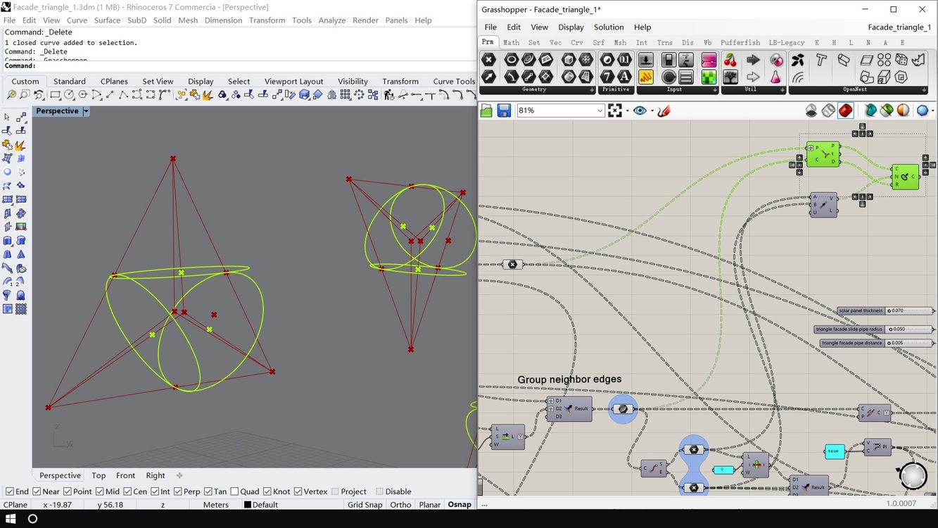
By now edges are grouped by meshes where they came from.
We add another level of group, group each with their next neighbor edge, as you can see in the list structure.

Step 7.
Join each set of edges, then explode, to unify their direction.

This is the key step !
We have to make “folding points” match “bone edges”, so I use “Path Mapper” to force their ordering.
Now we have desired point structure for constructing panels!

Panels are created. Let’s bake them to check their direction
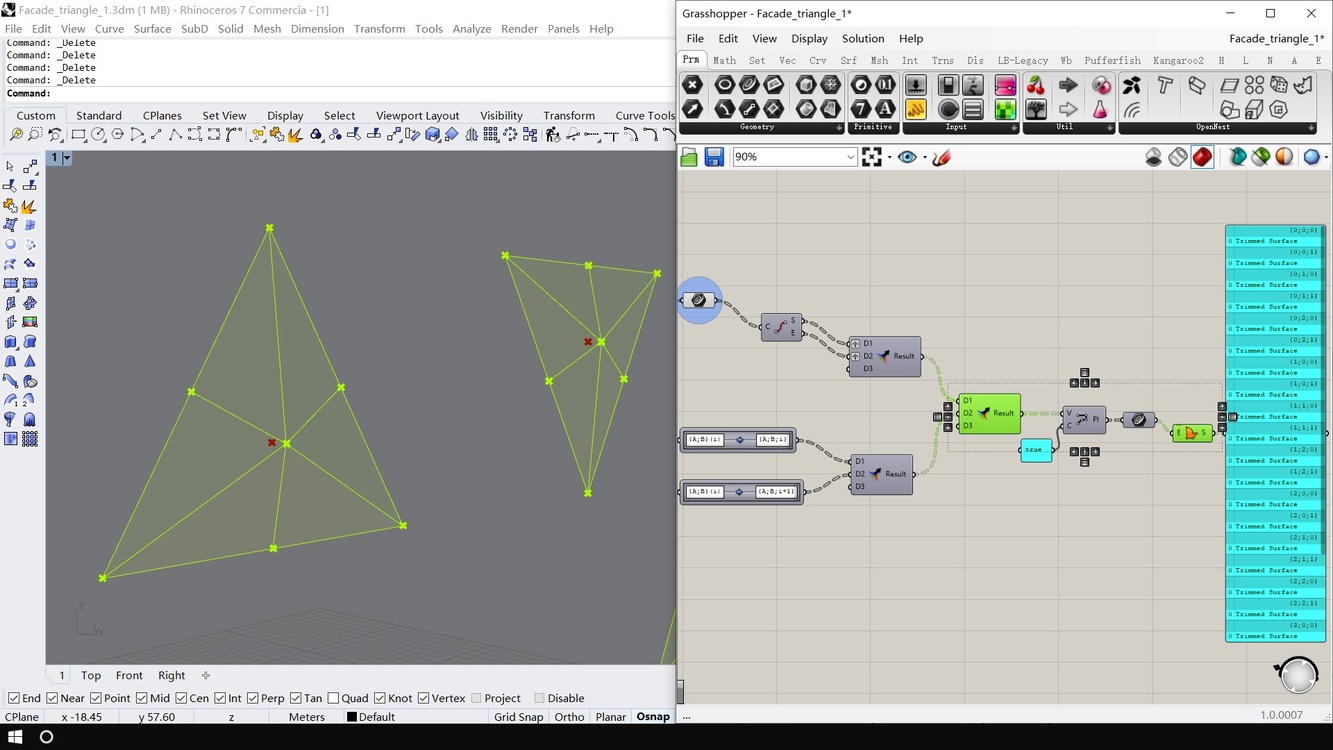
As you can see each set of faces has a reversed one (Because surface direction is decided by boundary point direction, and anticlockwise point direction is considered front). We have to unify them…

We need to create referencing surface to flip them , so let’s get back here and create these “large triangles” with neighbor edges, then bake to check their face direction…

Turns out it’s their back side…

We can’t believe in luck, we need a reliable way unify face directions.
We can do this by checking “which side of the surface the referencing point lives”.
Remember “mesh center”? We need them now.

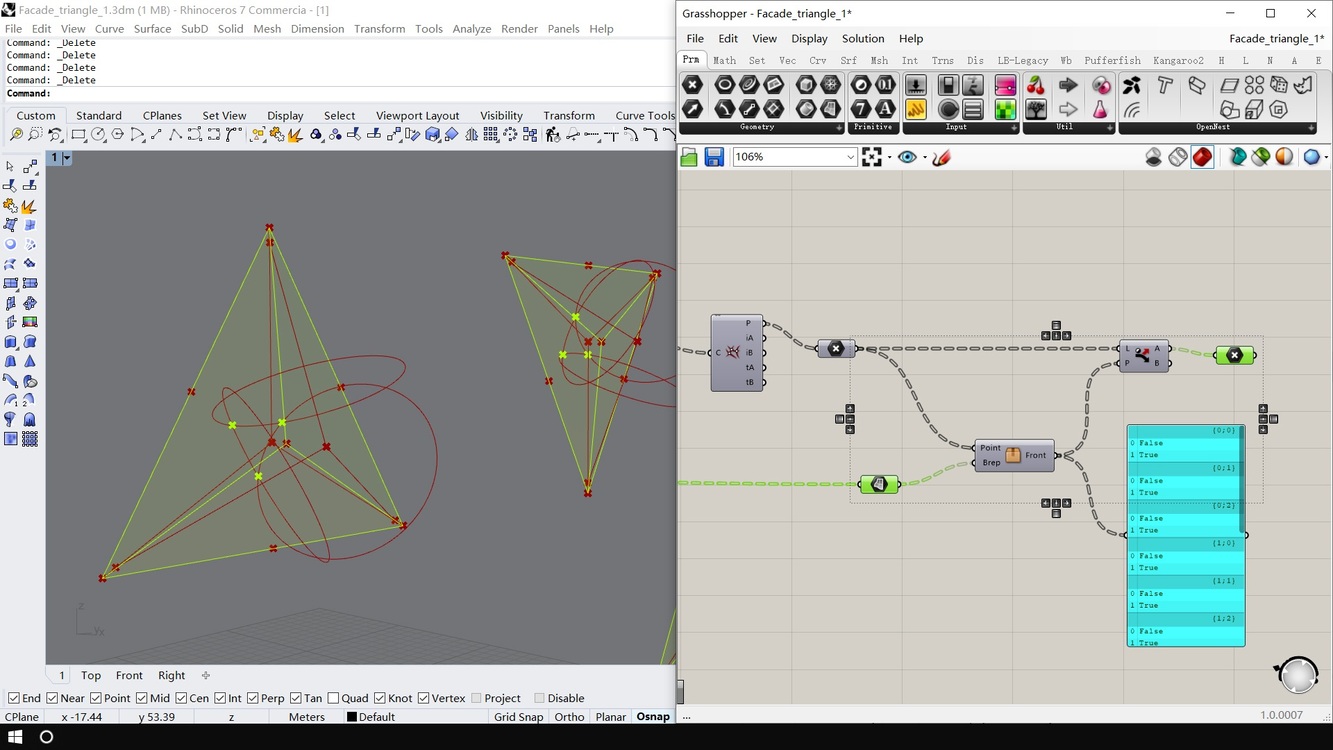
This bunch of nodes can help to deside point-surface side. We call this tool “Point_Brep_Side”.
Let’s see what’s inside…
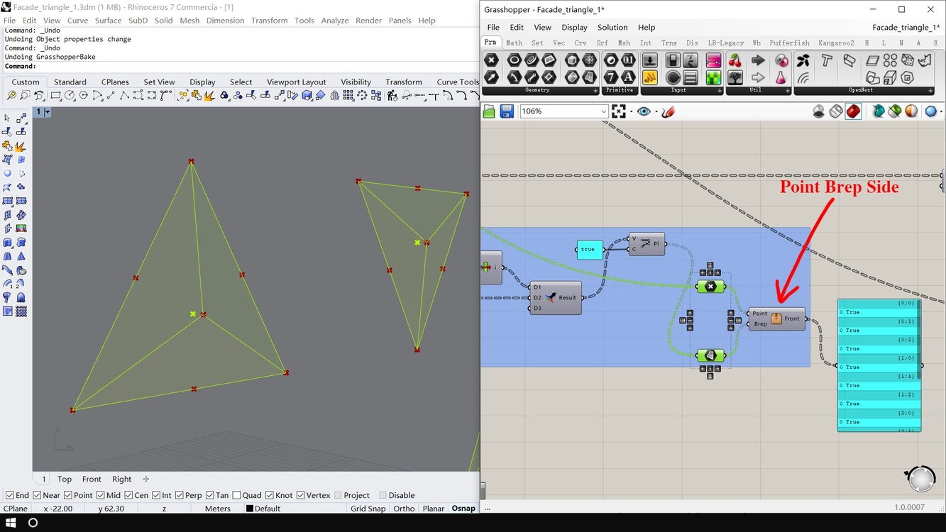
It’s simple.
Project point to that surface, check angle between projection direction and surface normal, if the angle larger than zero (to avoid error of accuracy, I use Pi * 0.01 to represent “zero”), then output “true”, which means it’s in front of the surface.

Now we got point-surface side, we can use “Filter” to see if we need to flip this surface!
BUT… BUT..

It doesn’t support multiple path! (Which idiot designed this s**t ?)
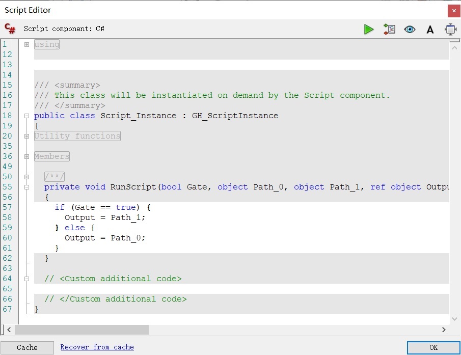
OK, I will do it on my own…
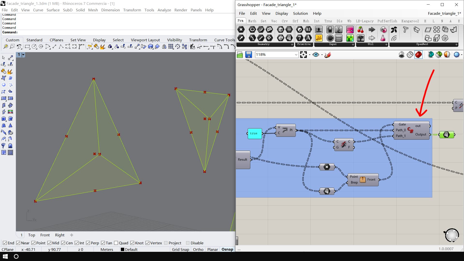
With C#, this can be easily done!
Bake again, now “large triangles” are flipped as we wanted!

now we flip these “panel triangles” with “large triangles” as guide.
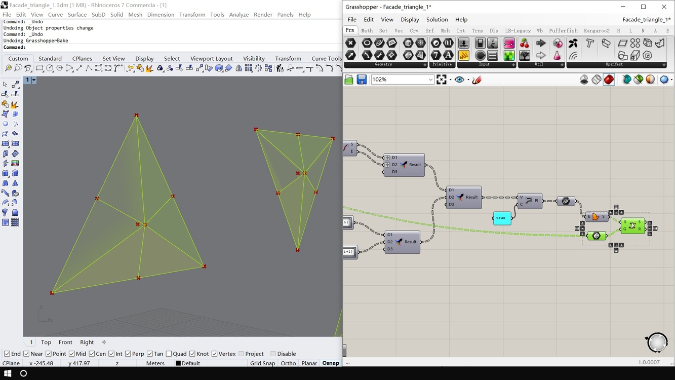
Bake !
And perfect !

Step 8.
Now we can make some decorations on these panels, like offset inwards to avoid colliding
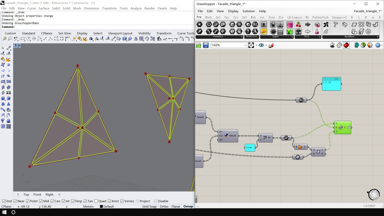
Bevel the corners (Here is how to bevel: Bevel Tool), then give them thickness… Again, GH doesn’t support offset with thickness, We also need C# to get it done

Here’s the code
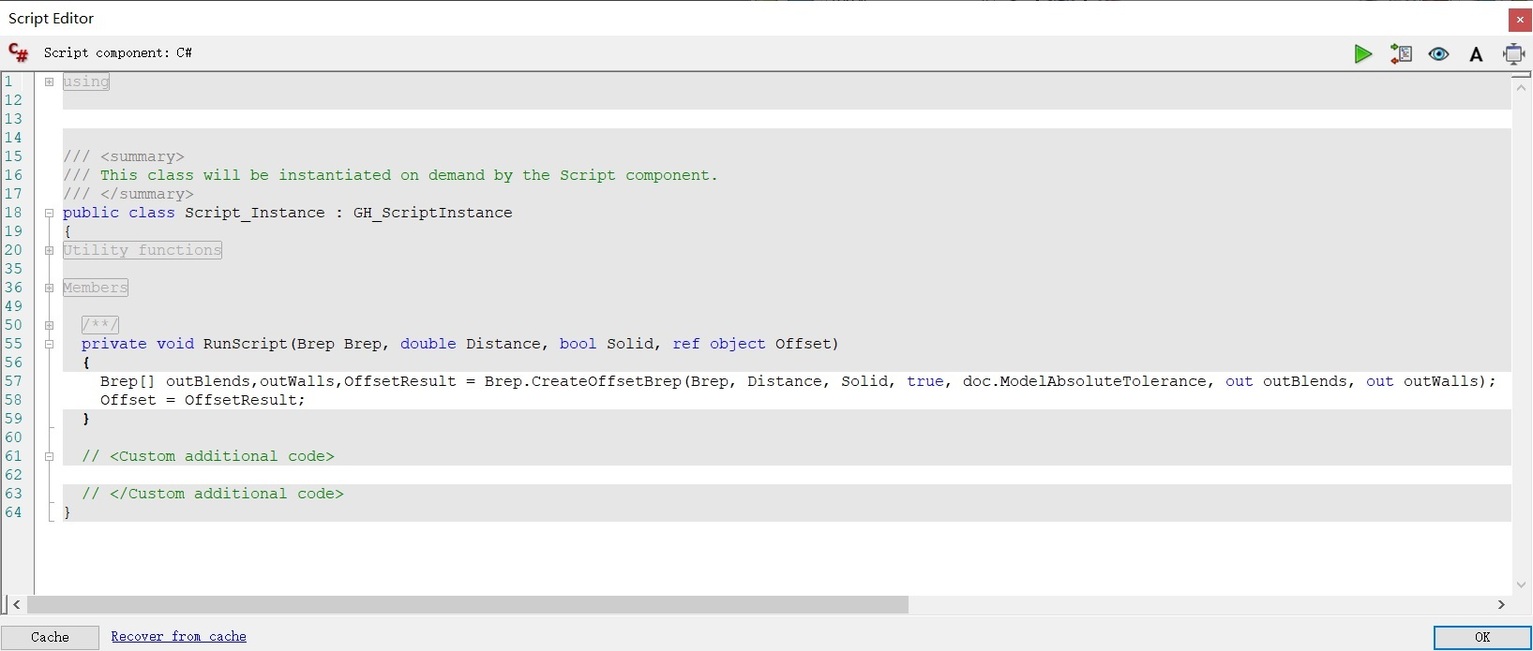
Then move them upwards along their normal, to give space for installation. Panels are done !
Of course you can make further decorations, but I won’t spend more time on this. Let’s move on.

Step 9.
Now, the most challenging part: Make them foldable.
While convex centers elevating, one side of “bone edges” will be elevated upwards meanwhile the other side will be sliding on rails on mesh plane.
Panels are hard plates, which means they can’t be stretched, so they must move with “bone edges”, and fold inwards at the same time.
For this, we need 3 points to locate panel movement: “convex center”, “folding points” and “sliding points” (Don’t worry, I’ll make these clear)
Here, remember “folding points” in Step 4? We need them again. Get the projection distance of each folding point, and find shortest distance in each group. This distance is for deciding the maximum elevation height.
Why do we need this?
Because “elevation height” can’t be a random number, or panels may collide or can’t completely open. We need a solid way to find it.
OK, but why “shortest”?
In this case each triangle is equilateral triangle, so all 3 distances are equal. But in real project these triangles may be distorted, when you apply this to non-equilateral triangles, these 3 distances are not equal, to avoid colliding, we can only elevate them by the shortest distance.


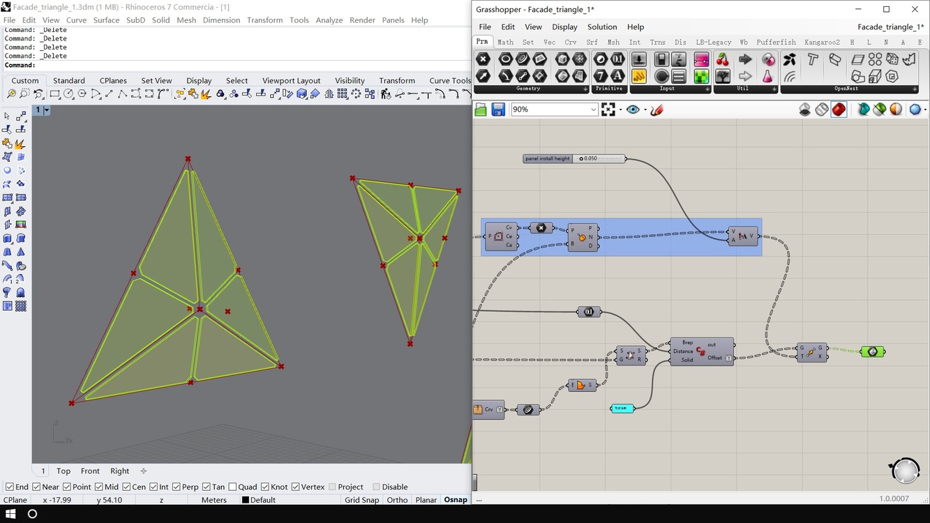
Elevate “mesh center” along mesh normal by elevation height.
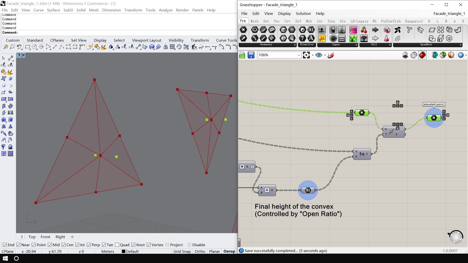
Now we have “mesh center”, “convex center” and “elevated center”. We need to repeat them (by 3) to match the number of edges

Step 10.
Now, take “triangle inner edges” and get the number of edges in each set (which is 3).
Actually, you don’t need this step, just use fixed number “3” if you like.
I did this in order to make this system flexible for future enhancement (Such as change triangle to quad…). After all, fixed number in procedural design is always unreliable.


Now we have repeated points in each group by 3.
Use “mesh center” to make lines on base mesh, they are the rails that “bone edges” will slide on. We call them “base rails”.

But how do we know where the sliding point lies?
Use sphere to intersect with “base rails”.
The length of the “bone edges” are fixed, so we generate sphere on “elevated center” with radius equal to length of corresponding “bone edge”
Now we have intersections as “sliding points”

Then we also need the points to match the list structure of “grouped neighbor edges”, so we use this trick to make their list structure match (make plane, then extract center).

Connect “elevated center” with “sliding points”.
Now we have located the “bone edges” !

Animation works fine

Step 11.
Final Task: Locate the “folding points”.
Project “folding points” to “original bone edges”.

Then create circle on each “projected point” with “bone edges” as normal direction, “project distance” as radius.
Now we want to orient these circles along with “bone edges” while “bone edges” are moving. So, Where to find the “target plane”?

Here it is.

Now the circle moves with “bone edges”.

Then make circles intersect.


Use the tool “Point_Brep_Side” tool we created earlier to check point-surface side, and only keep points on the back side of the surface.
Then we use “moving bone edges” and “elevated center” to create “elevated planes”.

Same way, using “original bone edges” and “convex center”, “original planes” can also be created.

Finally, orient the panels from “original planes” to “elevated planes”.
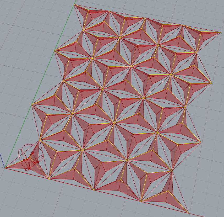
Success !!!

Beautiful isn’t it?