Is there a better way to draw a bevel gear?

I’ve had success using Thomas Anagnostou’s Gear Generator script to draw spur gears, but drawing a bevel gear has me stumped. I’ve generated the curve easily enough, but extruding the curve to generate the surface has me wondering. Maybe it’s this slow machine that doesn’t allow the object to be drawn in what seems to me to be a reasonable amount of time.
I generated a surface using sweep 2 rails above the curve to serve as a boundary to extrude the curve to and an angled line to serve as a path from the quad of the pitch circle through 135 deg to the Z axis intercept. I chose Surface>Extrude Curve Along Curve and used the line just drawn as the path along which to extrude to the boundary. I selected the path curve near start ( Solid=Yes DeleteInput=No SubCurve=No SplitAtTangents=No ). The last thing I saw on the command line was: ‘Splitting… Press Esc to cancel’. Rhino is locked up (Not Responding) so I thought I’d take a break for a sanity check. Is there a better way to draw a bevel gear? I saw Ian’s post about A new involute gear generator but I think I’ll try to get Gear Generator figured out first.
Thanks in advance.

Edit: I just now tried Surface>Extrude Surface To Point (To Boundary). That seems to work much better.

Are you creating the surfaces for all the teeth at the same time; or are you creating the surfaces for one tooth, using ArrayPolar to copy those surfaces for the remaining teeth, and using Join to join the surfaces?

Thank you davidcockey.

Short answer: I am creating [quote=“davidcockey, post:2, topic:29485”]
the surfaces for all the teeth at the same time.
[/quote]
After GearGen created the curve, I exploded it to separate the curves of the teeth, and added fillets to the dedendum of a tooth profile in a convenient (along an axis) location. I had to change the Construction Plane in order to add the fillets of the bevel tooth profile. I then restored the CP to it’s default by using _4View twice.
I then joined the adjacent curves that comprise the profile of one tooth, deleted all the other curves comprising the remaining teeth, selected that joined curve (which is both sides of the dedendum of one tooth and the crown of the appendum of the adjacent tooth) and used ArrayPolar on that tooth the desired number of times about the origin in Top view. I then created surfaces for all the teeth at the same time. I gather from your question that I might have better results by creating the surfaces for one tooth and THEN use ArrayPolar and join those. Is that correct? That seems to be a much better approach from a system resources standpoint.
BTW, anyone reading this who is about to upgrade their system and would like to sell me their old system, I’ll bet that their old system is better than what I’m using now. If that’s the case, I would encourage them to message me about it.
Thanks

Try creating the surfaces for one tooth and then use ArrayPolar and see how much time it takes compared to creating all the surfaces at once. My guess is creating one surface and using ArrayPolar will be faster.

1 Like

Awesome! Thank you.

Update: That made all the difference in the world, David. Thanks. Now I’ve got another issue.

After creating the surfaces for one tooth (I used extrude to Point, then trimmed what I didn’t want) and using ArrayPolar, I attempted to join the surfaces. Here’s what I saw in the command line:
“Command: _Join
Surface join in progress… Press Esc to cancel
130 surfaces or polysurfaces joined into one open polysurface.
Joining curves.
Unable to join curves.”

Please see Bevel_Pinion_gear_02_29_16 005.3dm
Bevel_Pinion_gear_02_29_16 005.3dm (1.8 MB)

So, for some reason Rhino was unable to join curves.
I suspect that that might be due to the fact that I scaled the curve generated by Gear Generator by the ratio of a line drawn between the midpoint of bottom of the dedendum to the midpoint of a line drawn across the space between addenda (sp?) of adjacent teeth of the curves on the pitch circle.

Please see Bevel_Pinion_gear_tooth_profile_on_pitch_circle_02_29_16.3dm
Bevel_Pinion_gear_tooth_profile_on_pitch_circle_02_29_16.3dm (33.0 KB)

However, when I select the polysurface it looks okay. Should I be concerned? Will this bite me when and if I send it to a machinist?

I did an ArrayPolar of your profile curve to create 130 of the curve, and they joined into on closed curve without any problems.
Bevel_Pinion_gear_tooth_profile_on_pitch_circle_02_29_16_DC.3dm (314.2 KB)

Thanks, David.
Joining the curves is not the problem. Do you remember the issues I was having with Rhino crashing when I tried to extrude the result of ArrayPolar having been joined? The problem was due to the Intel HD Graphics on this Gateway Notebook. I don’t think I mentioned it then but it was on the main gear which had 300 teeth.

You suggested I create the surface of one tooth by extruding the curve, then joining those extrusions. Joining the extrusions was where I was having trouble.

But it’s all good. I’ve been fiddling with it and I think I’ve gotten something I can use.
Will I be able to repeat it? I don’t know.

Bevel_Pinion_gear_03_02_16_DW.3dm (2.3 MB)

What about the commands FlowAlongSurface and than Orient (with scale) and Loft (natural) to get a bevel gear? The FlowAlongSrf command makes it possible to turn all the teeth of the spurgear curves. See attached rhino file. In the layers I descripe the steps.


fig 1 help surfaces for FlowAlongSrf.

fig 2 FlowAlongSurface. ( Copy=Yes Rigid=No Plane ConstrainNormal=No AutoAdjust=Yes PreserveStructure=No )

Fig 3 Orient with scale

Fig 4 loft (natural)

Fig 5 create closing surfaces (cones and planes)

Fig 6 Use the command CreateSolid (delete input: No)

Bevel Gears by FlowAlongSrf.3dm (9.4 MB)

The results looks nice, but is this as good as the official way?
Cheers,
Bas

3 Likes

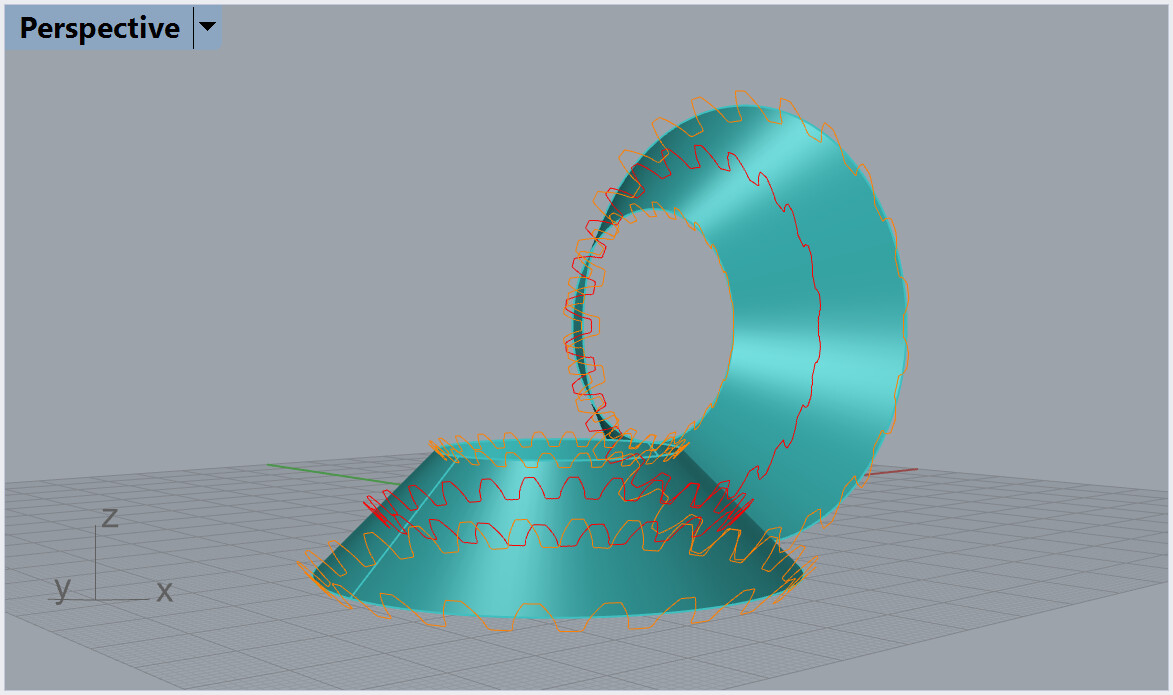
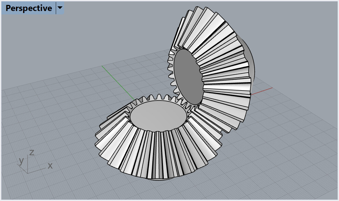
Hi Bas, I’ll look at your model soon. Just from your screen shots, it looks ok. I can see though that however you defined your module or diametral pitch (one is the inverse of the other), they are not conventional, because you have set the initial profile somewhere around the midway along the gear face.

I have inserted here the cut-down version of piece I wrote a couple of months ago on how module is conventionally defined for a bevel gear; starting with a few quotes.

Radzevich 2012, Dudley’s Handbook of Practical Gear Design and Manufacture: With regard to bevel gears “The specified size dimensions are given for the large end of the tooth. A bevel gear tooth that is 12 module at the large end may be only around 10 module at the small end.” (Page 26)

SDP/SI 2019, Elements of Metric Gear Technology : “Since bevel-tooth elements are tapered, tooth dimensions and pitch diameter are referenced to the outer end (heel).” (page T62)

Maitra 1994 Handbook of Gear Design, 2nd ed.: With regard to bevel gears, “The tooth data of a bevel gear are all given with reference to the large end[/color]”. (Section 5.1)

Oberg 1920 Spur and Bevel Gearing : “In speaking of the pitch of a bevel gear we always mean the pitch of the larger or outer ends of the teeth[/color]”. (page 202)

This convention has been in use for at least 100 years. All the stock gear manufacturers such as KHK and Boston Gear use the same convention in stating the module of their gears.

Actually, this convention is not arbitrary but is directly based on the basic concept of the bevel gear. As the excellent SDP/SI Elements of Metric Gear Technology explains, “Bevel gears have tapered elements because they are generated and operate, in theory, on the surface of a sphere. Pitch diameters of mating bevel gears belong to frusta of cones, as shown in Figure 8-2a.”. (The figure is worth looking at). So, the module is drawn on the surface of the theoretical sphere, which is the outer limit of the gears. That ‘back cone’, or ‘beveled back face’, which one sees at the ‘big end’ on bevel gears is a conical approximation of that spherical surface, and also intersects the pitch diameter.

In theory, the gears could mesh right to the centre of the sphere, but of course, they don’t. Where you cut off that inner end of the gear face is not theoretically established, but is a function of experiments with loading and so on. So you can’t set the module ‘midway’ along the gear face as a meaningful standard, because it would become dependent on the arbitrary choice of face width. And so, it is definite that the module, in bevel gear theory, is only located at the ‘large end’ of the gear wheel where everyone expects it and can find it very easily.

1 Like

@ Ian
Thanks for your long and precise answer.