Hi, All.
I want to trasfer textures to facade like the image below. I can not find tutorials to to it . Could anyone tells me the steps? Thanks very much.
It seems only surface morph can not help in this kind of facade with bumps

Hi @Flora,
If you really want to transfer a texture to for instance a mesh, you first need to UV-unwrapped (flatten) the mesh, create a custom material, and then apply the textures with the material. In Rhino 6, you can apply Color, Transparency, Bump, and Environmental textures.
SrfMorph has nothing to do with it though. ![]()
If you rather want to map some sort of geometry - for instance a panel or module - to your base mesh or surface, “texture” would be the wrong term, I guess.
Since this seems to be a polysurface, a geometry composed of different individual sub-surfaces, or triangular mesh, paneling really can’t be applied like you would for a untrimmed, singular surface. You have to deal with each sub-surface or face in case of a mesh. It usually helps, if you’re panel already roughly follows the overall shape of the geometry it gets mapped to, in this case planar (?) triangles.
I guess we at least need to see the “texture” in order to be able to provide further help.
If you have a GH file, I’d post that too for good measure.
Hi, Thanks Diff for your help.
yes, I used a wrong term ‘texture’ for what I want to do. Right now I have this polysurface converted into grasshopper file, and going to make my panel the following hours. I will post my panel once done. currently at least the base is there.like following image. (though my methoud maybe not quite clever)
My difficulty is as you mentioned, ’ You have to deal with each sub-surface or face in case of a mesh.’
Look forward your help in next step.
OK, post you module once you’re done.
Hi, Diff
(or someone who have spare time  )
)
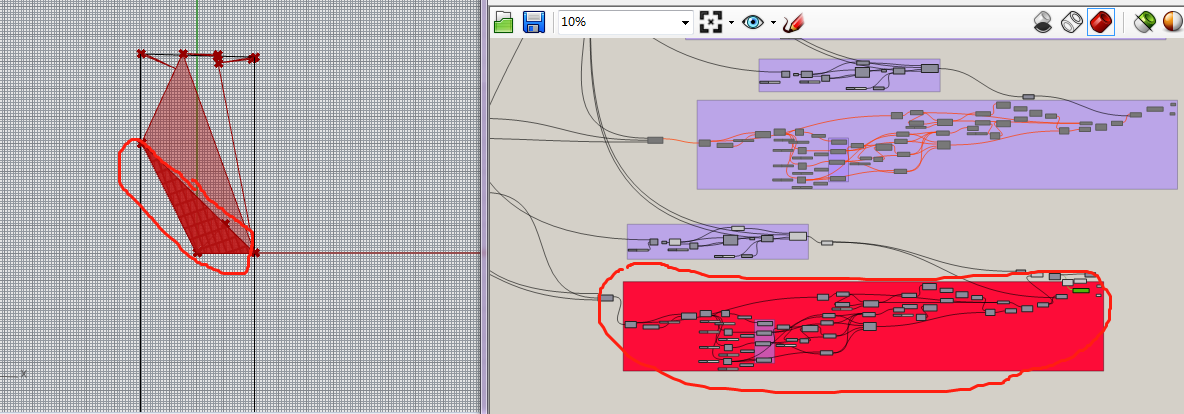
I have been trying to map geometry to the poly surface. some succeed, while when I use same principle to the circled part, it failed. I am finding problems now with no answer at the moment. Could u or some others help to check where is the problem? Thanks very much!!
My method is rotate the geometry with different angle align with the pieces of facade.
I have upload my document here20201221 tower facade.3dm (158.3 KB)
20201221 Facade.gh (196.2 KB)
Flora, there’s no need for double posting! Sometimes you just have to be patient.
I’ve looked at your files and holy moly this is a lot to comb through. Could you maybe upload a reduced version with only the relevant parts?
That said, it’s quite hard to see what the problem is exactly. The thing you show in your screenshot seems to be different from what’s in your file? Also, there is pattern that’s being mapped, but I fail to see where something is amiss! To me it looks fine, could you explain a little better what you want to do differently?
Hi, Diff.
Thanks for remind me no duplicate post. I’m not familiar with the post rule so afraid this reply can not be seen, sorry  And, thanks for your time and patience
The problem is, 1.although I use solid difference can get the area I need, it need extra step to extract the panel part from the cutter; (method 2)
2. other parts of the panels follow another method(method 1), while it fails here, that’s why I use solid difference here. I wonder, why previous method can not applied here correctly. The method is this: 1) generate my panel on one piece of facade components, 2) then I rotate this panel from that piece by angle between exsiting panel and target one.
The following image I marked method 1 & 2. I would like to use method 1.
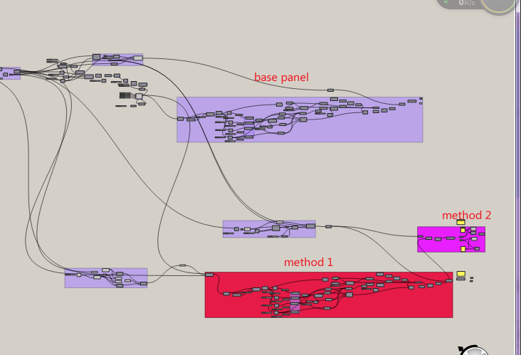

The cause of the problem I observed is : Cutter is no succeed in method 1 , need to check out.
Hope my explaination can be easily understood.
Here is my simplified document. THANKS!
20201222 Facade.gh (86.7 KB) 20201221 tower facade.3dm (182.9 KB)
It’s like the law, not knowing about it, doesn’t exempt you from it. ![]()
Thanks for clearing things up! I’ll take another look tonight.
Just to be sure, am I right in the assumption that you want to make the trimmed grid cells match up between different, adjacent brep faces to get an overall homogeneous pattern, or is simply trimming them enough?
Hi, Diff.
Thanks very much for reply  !
!
Your assumption ’ to make the trimmed grid cells match up between different, adjacent brep faces’
is what I really want to do 
I tried on upleft and upright breps, and succeed, while when came to this piece, failed. So I would like to find out why. Hope this will not bother you much, thanks!
Hey,
I had only little time yesterday, but I’m going to take a serious look at your stuff in the afternoon today. The task at hand is probably harder than expected, so no promises. 
Nobody else taking a shot at it, is probably already a good indicator of the skill level required.
Would you mind if part of the solution would be scripted in GHPython?
HI, Diff.
Thanks for your reply!
Yep, maybe this takes time so no others can help at this holiday time.
I am not quite familiar with GHPython, totally layman😂, but I think I can take it as a chance to learn, if u willing to spare your time. Actually I am a starter for GH as well😅. So any help will be appreciated !
If u are extremely busy, just tell me, I will try by my best to solve my own problem.
Thanks very much again!
diff-arch via McNeel Forum <mcneel@discoursemail.com> 于2020年12月23日周三 下午8:45写道:
I have updated my script after so long time’s studying on GH. I find that, my original script has some mistakes in plane origin and some unnecessary steps in finding edges/extending curves, ect. So unexpected situation happens
After combing all problems , now I successfully transfered geometric shape onto this surface by rotate the geometric shape with different angles along each edge.
If some one need to know how to transfer, can leave a message