I’ve made this candelabra structure for 3D printing:
Because of all the small details the print will take about 36 hours to complete. So I want to print it only once. But before that I’m stuck on how to add some decoration to the base ramp part:
This is a Closed Brep (the whole structure is a series of Closed Breps) so it should be amenable to various ways to make it look a bit better. My first thought (not a great one) was to poke holes all over it, maybe in some sort of pattern. But there should be a better option than this. I’ve never tried using the Paneling Tools or LunchBox add-ons. Or is there something else that might be better? I’m a bit concerned about the way it comes to a flat edge in the inside - maybe I should make a short vertical face there instead. I’m not expecting anyone to do any actual work on this - I just would like some suggestions on how I might proceed.
How about doing a tree like structure with a flat surface on top? I don’t know if that makes sense. And I don’t do any 3d printing so it may not even be possible.
Here is a link to a post that could kinda show what I mean.
Thanks Joseph - I may end up using your approach. I had the idea if using one of my old methods of using SrfMorph to map raised rectangles onto a Brep surface, but I’ve run into an old quirk about trimmed surfaces retaining their full untrimmed size.
The base is made by extruding the top surface downward, which ends up looking like this:
Of course I only want to top half of this, so I split it with a large planar circle surface at Z=0. But when I SrfMorph onto the 2 vertical faces of the base I get this:
The problem (of course) is that the trimmed faces retain their original size because (paraphrasing an old post from David) that’s just the way Nurbs surfaces are. So I’m going to see if I can go back in time and find the solution to this. I remember seeing it once - but that was long ago and my memory isn’t what it used to be.
Thanks Ryan - Laurent’s work is always pretty spectacular - not to mention a bit beyond my level of expertise. Those organic tree-type diagrams are fascinating for sure, but I don’t yet see how something like that could be applied to my current project. (My reply to Joseph explains the basic problem I’m stuck on at the moment.)
Maybe my next one can make use of the tree concept. I think MultiPipe would eliminate the need to smooth out the junction pints of the underlying line segments.
Nice try Joseph - I fell into that same rabbit hole. That method doesn’t work because the surfaces resulting from the split retain their original size.
I just discovered a method that does work. After joining the giant results like this:
Might be better with fewer, larger holes? Faster too, only 12+ seconds for SDiff, I added a ‘Move down’ slider to shift all the points (holes) downward as there is extra space at the bottom.
I didn’t realize until examining your method that it’s the morphing code that uses the full/original surface geometry. I still don’t understand why SrfMorph was coded that way, but I expect it relates to David’s old comment about Nurbs surfaces always retain their original shape. “always” is the key word there.
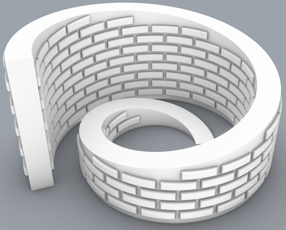
Your approach places the bricks directly, without morphing them. That gives a different final effect - the bricks look like real bricks with flat surfaces, not curved surfaces that morphing would produce. That’s a valuable difference and, for 3D printing, could be useful with a different base shape.
There is a 3D printing problem with your flat sided bricks - the protruding bottom surfaces can’t be printed because there is nothing holding them up. A 3D print is constructed from multiple horizontal layers - each layer is a series of 0.4 mm diameter loops of extruded plastic. Each new layer has to be extruded on the top of the previous layer - otherwise it droops and looks funny. That’s why the “bricks” on my version have sloping sides; the slope is carefully made so that there is enough contact from layer N to fully support layer N+1.
So I guess holes are forbidden also? 3D printing appears to be severely limited.
P.S. I have nothing against SrfMorph and have used it in the past. No doubt it can be adapted to use the staggered brick/hole pattern I have suggested. As to the limits of 3D printing, that’s your business, I don’t have a 3D printer.
Here is a way of getting curved bricks without SrfMorph, then filleting the four visible edges. Is it printable? I don’t know. Just riffing on ideas to answer your thread title question.
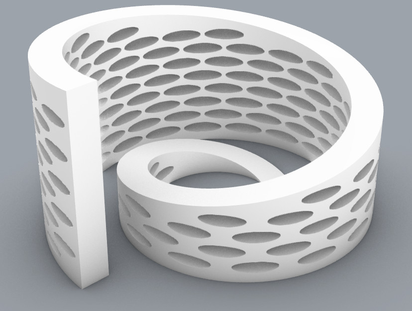
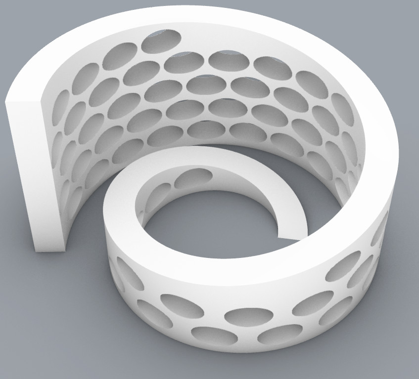
Actually holes are OK if they are carefully designed:
In these cases the holes are ellipse with the long axis vertical - to minimise the size of the unsupported area. In the first case all edges filleted, but not in the second. If you look at the 2nd image in the PerfVase1 link you’ll see ugliness around some of the holes. That’s when I realized that filleting the edges of all the holes would help. For Meshcontainer1 I guessed at the fillet radius and should have made it a bit larger.
The morphing distorts the ellipse quite a bit, and you don’t see the cleanup I did to neaten up the tops of some of the holes. Also, for the top one I reduced the thickness of the solid sides, so there aren’t many loops that are subject to malformation.
Filleting is a good approach for allowing holes, and I’ve done that several times. The key to success is positioning the tops of the filleted hole makers so that the tops of the printed holes require few and short lengths of extruded filament.
Merely parameters, as is the choice between fillet and chamfer.
I have no interest in 3D printing small models. This 3D printer, on the other hand, is VERY INTERESTING to me: “80 feet long by 25 feet wide by 10 feet high.”