How do I identify vertices along a (mesh) crease?

So I manipulated a mesh by moving some vertices around, but in doing so I accidently move also vertices that belongs to “creases”, or would you call it edges?

Anyway, how do I identify such edges/creases using RhinoCommon/GrassHopper) that must not be moved in order to preserve the geometry (term: topology?)

Fig.1. The dent along the box edge - no good, no good.

// Rolf

Hi Rolf,

in case of your box it appears the edges or vertices are partially naked. To determine and exclude these in your transforms look out for:

Mesh.GetNakedEdgePointStatus 
Mesh.GetNakedEdges

_
c.

Hi @clement,
I did a Dispatch of the points based on Mesh.GetNakedEdgePointStatus (bool array) and the result is puzzling, Point all over the mesh are considered naked.

Fig.1. These are reported as NakedEdge-points:

Fig.2. And these are considered non-naked edge points:

The pattern is consistent though, so I must be doing something wrong when I triangulate the mesh.

Starting from a IsValid mesh, what I’m subdividing each triangle into four smaller triangles. Like so:

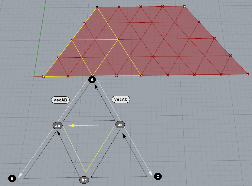
Fig.3. Subdivision pattern (Update: Fixed typo, +vectors):

This is a Rhino mesh, and obviously I’m doing something in the wrong order. But this test mesh (pictured) is valid, but when I sudivide the mesh Box pcitured earlier in Fig 1 and Fig 2, the mesh is not considered valid.

The code is straight forward (following the pattern shown above):

    public void SplitFace4(Mesh m, int faceA, int faceB, int faceC, double t)
    {
        //
        // SPLIT EDGES IN HALF
        //
        //     /\
        //    /__\
        //
        //     /\
        //    /\/\

        //
        // Face corners
        //

        var ptA = m.Vertices[faceA];
        var ptB = m.Vertices[faceB];
        var ptC = m.Vertices[faceC];

        //
        // Find split point at mid points along the edges
        //

        var vecAB = new Vector3d(ptB - ptA);
        var ptAB = new Point3d(t * vecAB.X, t * vecAB.Y, t * vecAB.Z) + ptA;
        var vecBC = new Vector3d(ptC - ptB);
        var ptBC = new Point3d(t * vecBC.X, t * vecBC.Y, t * vecBC.Z) + ptB;
        var vecAC = new Vector3d(ptC - ptA);
        var ptAC = new Point3d(t * vecAC.X, t * vecAC.Y, t * vecAC.Z) + ptA;

        //
        // Add the new points to the mesh
        //

        var i_ab = m.Vertices.Add(ptAB);
        var i_bc = m.Vertices.Add(ptBC);
        var i_ac = m.Vertices.Add(ptAC);

        //
        // INSERT SPLIT FACES
        //

        // Top     /\
        m.Faces.AddFace(faceA, i_ab, i_ac);

        // Bottom /\/\
        m.Faces.AddFace(i_ab, faceB, i_bc);
        m.Faces.AddFace(i_bc, i_ac, i_ab);
        m.Faces.AddFace(i_ac, i_bc, faceC);
    }

After the insertion of the faces I remove the old ones and run

m_mesh.Normals.ComputeNormals();
m_mesh.Compact();

< scratching head >

// Rolf

Your illustration shows 2 pts “B”, which I assume is just a typo, and the lower right-hand one should be “C”.
I also think there might be a small conceptual confusion in that the intermediate points should be labelled “ab”, “bc” and “ca”.
Aren’t these triangles actually loops? Don’t the vectors all need to go around the loop in the same direction (CW or CCW)?
That leads me to believe that
var vecAC = new Vector3d(ptC - ptA) should be
var vecCA = new Vector3d(ptA - ptC)

It has been a while, however, since I’ve done stuff like this, so I may be all wet here.

Yes, typo.

The vectors aren’t defining the loop, only the vertices are (or their indices). The vectors are used only for calculating the split-points on the edges, and therefore it doesn’t really matter which way between two points are being used (at least not when splitting at parameter 0.5 as in this case). Edit: I think I originally used the vectors also for testing face Normal direction by calculating the CrossProduct for the “two legs” (hence A->B, A->C).

Edit 2: Just to clarify, despite the vector’s two-leggeness (ab, ac), the face corner points are clearly laid out in CCW order, as pictured with the arrows.

I was thinking that perhaps the start points of the loops could cause the “naked” vertices, but when I have tried different start points I couldn’t see any significant difference.

// Rolf

One would think so, wouldn’t one? When you visualize this stuff geometrically it seems like it wouldn’t. When doing the math, though, I’m pretty sure it does.

One thing I do remember from when I was working on meshes is that a little disciplined thinking goes a long way in staying organized.
Remember that a vector is a “directed line segment”, so it has direction and when calculating it the sign will flip depending on which point is subtracted from the other. This means that you aren’t doing exactly the same thing in each of your point calculation equations. (eg: var ptAC = new Point3d(t * vecAC.X, t * vecAC.Y, t * vecAC.Z) + ptA;)

Clearing this up may not solve your problem, but I still would like to suggest you maintain consistency in your calculations for sanity’s sake.

I appreciate good advice. However, changing the direction to CA only makes the internal triangles “rotate” when modifying “t” (I have a slider for that), which it was originally designed not to do.

In any case, the problem remains; vector’s going either way the resulting mesh is still invalid.

// Rolf

Hi Rolf,

use _SelNakedMeshEdgePt to find out if these vertices are naked or welded. In both cases the mesh can be valid. Beeing valid or not does not have anything to do with naked edge point status.

For a subdivision like yours i use this very old vbscript. It handles triangles and quads and does not create naked mesh vertices unless the splitted edge is naked.

MeshSplitNatural.rvb (8.5 KB)

_
c.

Since the mesh was Invalid I could not bake it, so that command didn’t do. :slight_smile:

However, I noticed that if I run m_mesh.Vertices.CombineIdentical(false, false); on the mesh, it becomes valid again. So now I can proceed with what I have. Let’s see how far…

// Rolf

That should do it, similar like _Weld would…

_
c.