I’d like to see which edges of a mesh are unwelded to define creases on SubD geometry.
How can I access this MeshTopologyEdgeList with a simple Python or C script?
I’d like to see which edges of a mesh are unwelded to define creases on SubD geometry.
How can I access this MeshTopologyEdgeList with a simple Python or C script?
Note: obviously you should add some topology (connectivity) info as well in order to do something with these edges etc etc
Note: you can do this as well in R5 with a few lines more and EF/FE connectivity (Weld: makes sure that faces sharing an edge and having a difference of normal greater than or equal to angleToleranceRadians share vertexes along that edge => vertex normals are averaged). But have in mind that vertex normals indexing IS NOT the topology vertex indexing.
Hi @PeterFotiadis Mesh topology could solve with Sandbox plugin, I also interested in unwelded edges but my code knowledge is limit, could you help me?
Er … you mean that you want a R5 solution? (the Method IsEdgeUnwelded is R6 stuff).
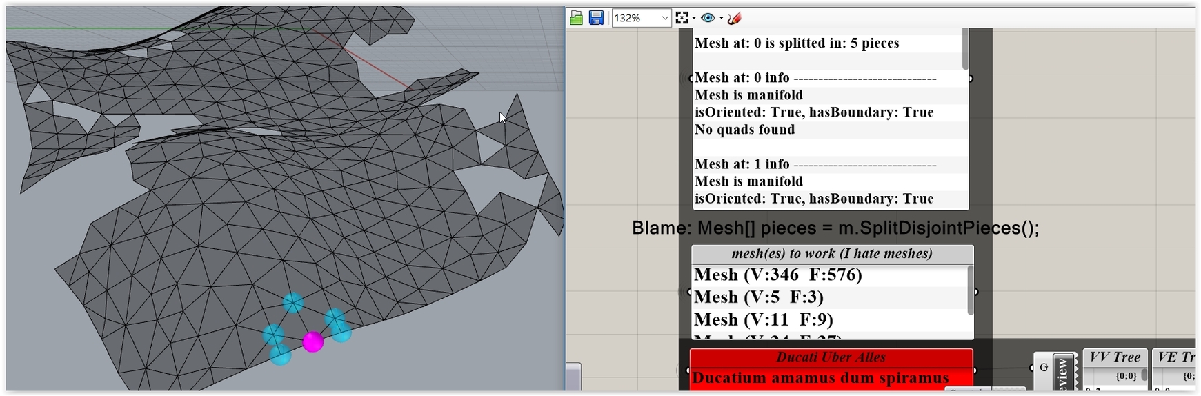
If so I’ll prepare a small C# demo soon (NOT using Sandbox) on “basic” Mesh Lists connectivity matters meaning obviously Trees with 2 dimensions (BTW: the trees that you can have are 9 since there’s 3 thingies to combine: TopoVertices, TopoEdges and Faces) and on the weld query as well. That said if you split a mesh in disjoint pieces (you always should check that - better safe than sorry) … then there’s a 2 dimensions connectivity around as well : for instance this mesh appears as one thingy … but connectivity wise is 5 thingies:
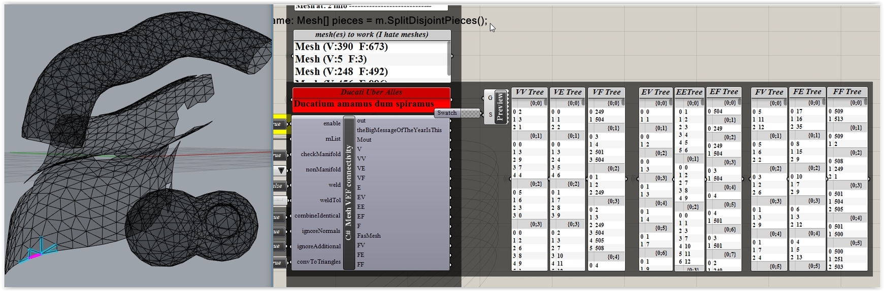
By small I mean a simplified version of that (does all the 9 conn Trees):
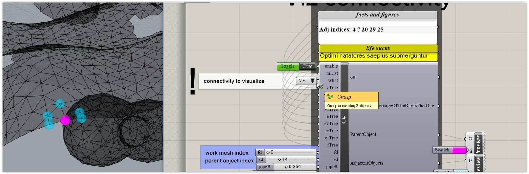
BTW: You want a C# like this as well? (visualize what connectivity is, that is):
Thanks Peter, I don’t understand yet.
How can I output the list with the unwelded edges?
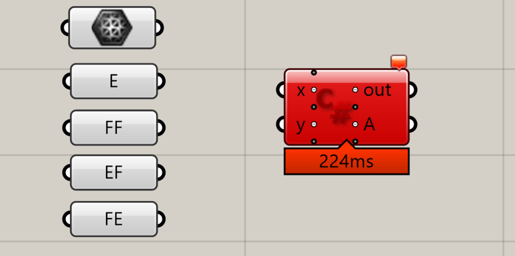
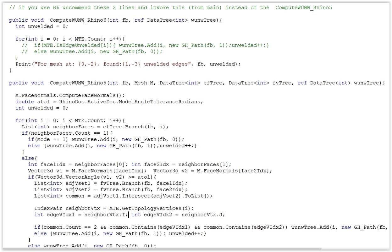
But … er … my dear Watson if you have R6 then the mini code in the first captured image (where M is your input valid, manifold - and not null - mesh) says it all: just “link” the edges result to an out C# parameter named, say, unweldedEdgesList.
I.E. unweldedEdgesList = edges;
Thanks Peter, I have R6 but no C knowledge. I get to this point very often where I know it should be possible somehow, if I only understood how to code.
I realized in the meantime that the weld command in Rhino shows which edges are unwelded….
Thanks again!
You are a wise man. Stay away from Dark Side matters and be a happy bunny.
In the mean time your def is ready (after removing a ton of internal stuff from one of my conn C#'s) it does 4 conn 2 dim trees [out of 9] and the weld/unweld clustering thingy [by index]. The disjoint job is included as well (should I add a quad> tri check/conversion?). However extensive tests for the validity of your input ARE NOT included: avoid feeding the thing with bananas.
But since I never work with meshes (other than in tensile membrane cases) I don’t have properly bad meshes : can you provide some for the BETA testing? (better safe than sorry). Some freaky/ugly/unspeakable meshes could be handy as well (in The Name of Science).
best
Awesome @PeterFotiadis, but first I need a MESH UnweldEdge with lines or points as an input, similar to this approach
Then, of course, verify the unwelded edge with another c#, thanks
What means unweldEdge?? You mean … er … on purpose making an edge (by index) an unwelded one? (adding possibly vertices to faces sharing that edge since unweld means that the faces MUST have unique vertex indices along that edge) . Kinda the inverse of that (used in the forthcoming C#):
And why to do that?
What means “lines or points” as input ?? You mean get points and do a mesh? … or maybe you mean that you want lines or points as output ?? - ie get the V, E Lists from a mesh.
the idea is to generate gaps, I think that the first step is to define the edges, then unweld them and finally move the vertices along the perpendicular edge.

Long way home for no reason:
BTW: On purpose unwelding edges has a meaning if you want to explode the mesh into submeshes where a submesh is a collection of faces that are contained within a closed loop of “unwelded” edges. Again: unwelded edges are edges where the faces that share the edge have unique mesh vertexes (not mesh topology vertexes) at both ends of the edge. That said a naked edge … er … hmm … is an unwelded one (otherwise the closed loop …).
For the unweld this edge thingy:
But truth to be said: I hate meshes like my sins.
BTW: MTV indexing is NOT the same as MV indexing (I hate meshes):
This means that another way to spot the unwelded stuff is to test this (i acc MTV indexing) that yields vertex indices FROM vertrex topo indices:
int VIndices = MTV.MeshVertexIndices(i);
if(VIndices.Length >1) … blah, blah
Peter, I don’t understand everything you posted in the meantime.
However, meshes are the gateway to SubD. So far, creases are defined by unwelding an edge. In my mind that’s a naked edge too, but I don’t think Rhino / Grasshopper developers would agree on this…
I mentioned the Rhino weld command shows which edges are welded and which are not but developers please the highlight is difficult to see on my 4K display.
Nor do I … but who’s gonna notice it? he he.
Get your stuff (NOTHING is internalized, load R file for the demo).
Mesh_EF_FV_and_IsWelded_EntryLevel_V1C.3dm (156.8 KB)
Mesh_EF_FV_and_IsWelded_EntryLevel_V1C.gh (135.4 KB)
NOTE: V1C is the latest (bug fixes) build insofar.
NOTE: Since I don’t have R6 the thing is geared towards R5.
In order to activate the IsEdgeUnwelded R6 Method:
Uncommend these lines (remove the //, that is):
Uncommend the R6 Method AND commend (add //) the R5 one
And since the task is over(?) … here’s some freaky things:
Maybe this image (reds are topo vertices indices) explains the freaky situation where 2 faces (the adjacent to a given edge [E666] according the EF connectivity) MAY yield 2 vertex indices Lists (blue) that have nothing in common (i.e. their intersection is an empty List) : meaning that E666 is unwelded (LOL*LOL):
BTW: The main C# thing does Lists of things (V, E, F) and 4 connectivity trees. If you enable the weldE then does the check (either in R5 or R6 mode as explained above) and puts unwelded edges indices in branch {x;1} and the welded ones in {x;0}. That said if mesh.Vertices.Count == mesh.TopologyVertices.Count … this means the obvious … but since we are talking milliseconds I haven’t use that as a by-pass first check. So what you get it’s a kind of connectivity: I do hope that you know how to use connectivity against a Tree (the E [edges] Tree in this case that is optionally made if the VEF var is set to 2).
BTW: Try Sandbox against the mesh List (mOut) : what does?
BTW: The main C# has the cIdent option : this uses a LOL void Method (mesh.Vertices.CombineIdentical(true, true)) that … er … removes all the vertices that are identical (kinda Kangaroo cleans dupe points). So … IF the mesh has unwelded edges … you get (cross fingers) a mesh with welded ones. BUT if the mesh is bananas this MAY yield a non valid mesh (if is the case that mesh is skipped - NOTE: if this happens the main dimensions in the trees are NOT according the indexing in mOut List [for obvious reasons]).
What all the above mean ? Simple: I hate meshes (and computers)
A naked edge is one that has ONE adjacent face .
A clothed unwelded edge is one that has TWO adjacent faces … where their vertices indices Lists (NOT topo vertices Lists) have NOTHING in common (their intersection yields an empty List).
Moral: LOL
Well … spend some minutes to “port” the unweld edge status check into a WIP C# that does that on purpose (alias MV: vertices, MTV: topo vertices, MTE: topo edges, MF: mesh faces):
![]() looks really well @PeterFotiadis adding vertices
looks really well @PeterFotiadis adding vertices
The EdgeIndices INPUT belong just the Interior Edges of MeshEdges, Is like this how could work?
In the case of EdgeIndices crosses, I think this could work like an “SplitMesh by EdgesIndices” by then adding this method Mesh.ExplodeAtUnweldedEdges, maybe with another C# not in the same script. Thanks again
If you are after stuff like making on purpose edges unwelded then you need the mesh.ExplodeAtUnweldedEdges Method. This has a certain importance in cases where you need to isolate mesh portions for further study: like pieces “near by” membrane anchor plates in tensile membrane designs (critical for a good looking membrane). But if you want to create just “gaps” like in the image that you posted above … well … we are killing mosquito(s) with bazooka(s).
But the edge unwelding is the easy thing (yielding a mesh that has more vertices than topology vertices [LOL]) . The big thing is to mastermind a variety of ways (as an option to the on the fly interactive selection of edges) to pick “edge paths” that make some sense.
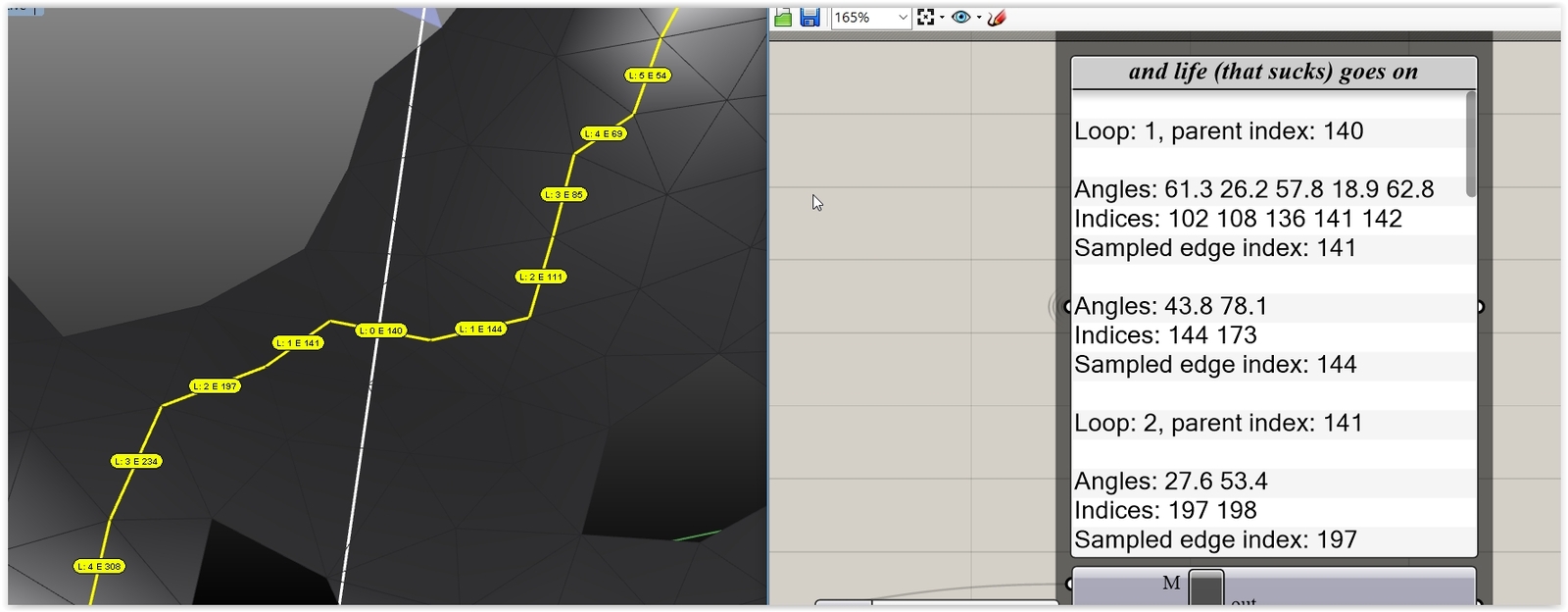
Here’s a WIP recursive way (when is 100% ready I’ll post it for you here): you define a direction (say via a rotated mesh Box, then via picking a Box XYZ axis) and a start edge Index and the recursion does the job for you by creating a kind of “chain edges collection”. Then you can make the edges unwelded (in fact the faces … but anyway) and get the mesh pieces (in fact … there’s a myriad of “what-if” cases … but hope dies last).
Hope that you know what is recursion: a freaky thingy where Peter calls Peter who calls Peter … who … until something happens and calls Jane (a far better option).
It is interesting using recursion to pick the edges by direction, but for now, I just need to kill mosquitos ![]() defining by Interior indices like your previous method (do not get me wrong, I would like to see both)
defining by Interior indices like your previous method (do not get me wrong, I would like to see both)
If it is like I mentioned before, I would be easy to generate that indices list of my specific needs, gaps and cuts predefined.